Implantable peripheral nerve stimulation lead

Active Publication Date: 2022-06-16
ADVANCED NEUROMODULATION SYST INC
View PDF3 Cites 0 Cited by
  • Summary
  • Abstract
  • Description
  • Claims
  • Application Information

AI Technical Summary

Benefits of technology

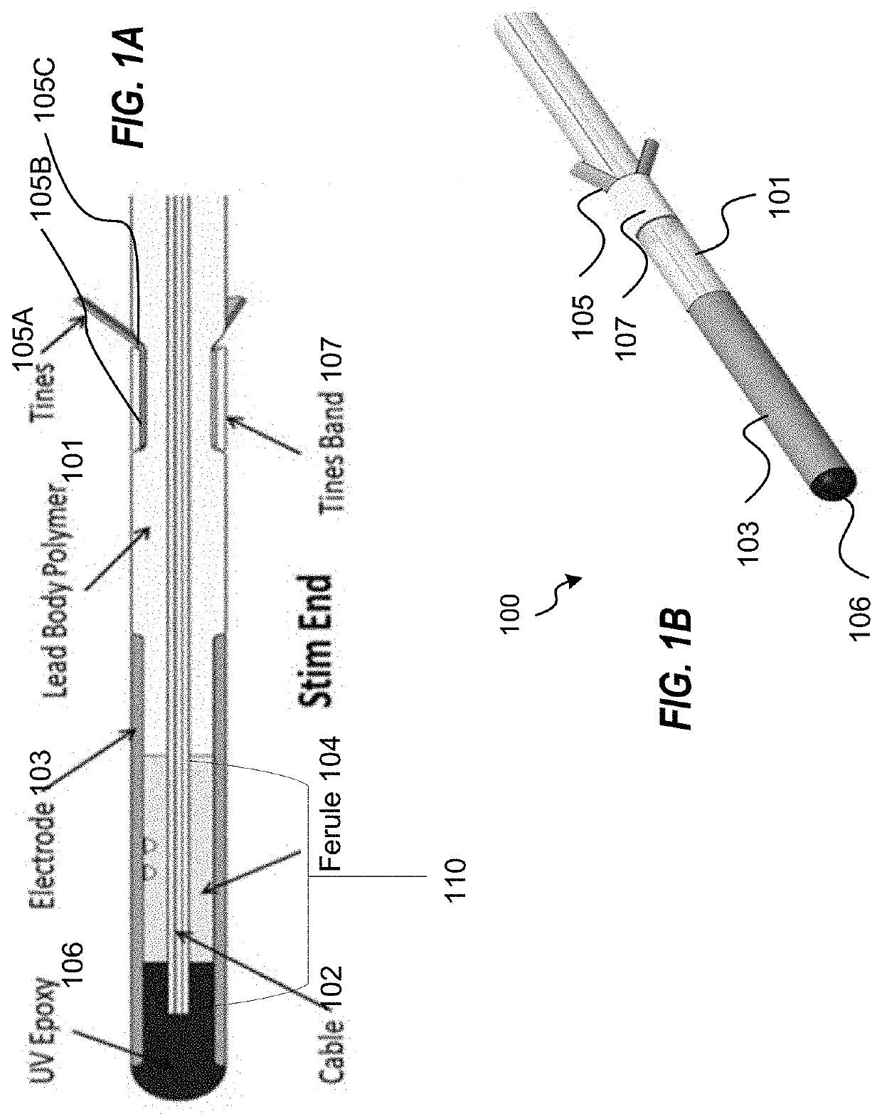
[0006]In some embodiments, a tine component may be securely attached (e.g., swaged) around a portion of the distal end of the lead body. The tine component may be configured to provide a retaining force against a force exerted in an extraction direction acting upon the stimulation lead, while allowing insertion of the stim end of the stimulation lead during implantation, and extraction of the stim end during explantation. For example, the tine component may include a plurality of tine features, also referred to herein as tines, that may be configured to fold down onto the lead body during insertion of the stimulation lead thereby allowing the stim end of the stimulation lead, including the electrode, to be inserted into the patient. The tine features of the stimulation lead may also be configured to remain folded at an anchoring angle away from the stim end of the stimulation lead. This configuration of the tine features provides a retaining force against the force exerted in the extraction direction, and maintains the stimulation lead anchored within the patient. In aspects, the tine features may be configured to fold up and back down against the lead body in the direction of the stim end when the force exerted is an extraction force of sufficient amount applied against the stimulation lead, thereby allowing the stim end to be extracted from the patient. As such, in aspects, when the force exerted in the extraction direction upon the stim end of the stimulation lead does not exceed the threshold, the tine features may remain in the anchor position and the retaining force may hold, thereby preventing the stim end from being displaced in the direction of extraction and/or extracted from the patient. In this manner, the tine component is configured to anchor the stim end within the patient to prevent accidental displacement of the lead in the direction of the force exerted in the extraction direction an

Problems solved by technology

However, the size of current implantable stimulation leads is not ideal for implantable solutions.
In addition, current implantable stimulation leads are cons

Method used


Image

  • Implantable peripheral nerve stimulation lead
  • Implantable peripheral nerve stimulation lead
  • Implantable peripheral nerve stimulation lead

Examples


Embodiment Construction

[0022]Unless defined otherwise, technical and scientific terms used herein have the same meaning as commonly understood by one of ordinary skill in the art to which this invention belongs. For purposes of the present invention, the following terms are defined below.

[0023]As used herein, the use of the word “a” or “an” when used in conjunction with the term “comprising” in the claims and / or the specification may mean “one,” but it is also consistent with the meaning of “one or more”, “at least one”, and “one or more than one.” Still further, the terms “having”, “including”, “containing” and “comprising” are interchangeable and one of skill in the art is cognizant that these terms are open ended terms.

[0024]As used herein, the term “peripheral nerve” refers a neuron or a bundle of neurons comprising a part of the peripheral nervous system. The nervous system comprises two general components, the central nervous system, which is composed of the brain and the spinal cord, and the periph...


PUM


Abstract

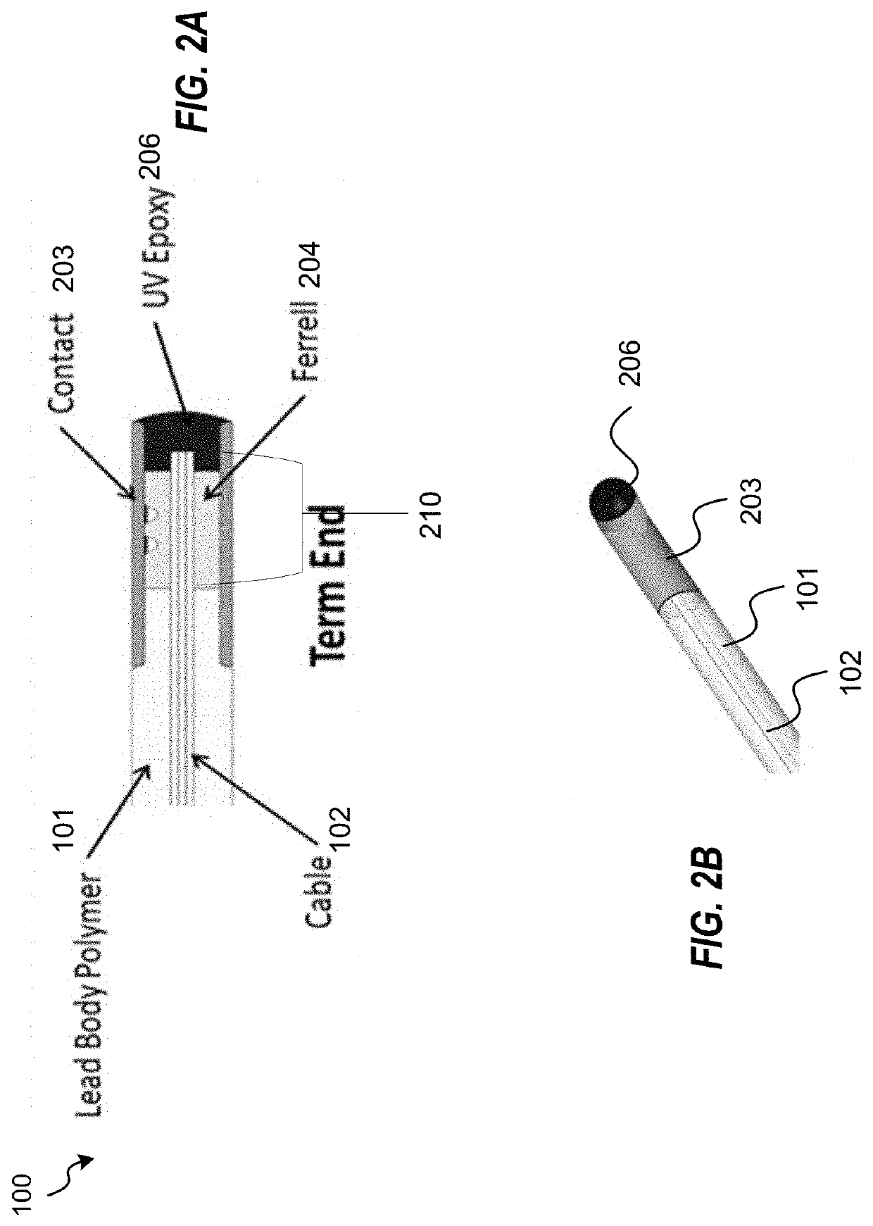
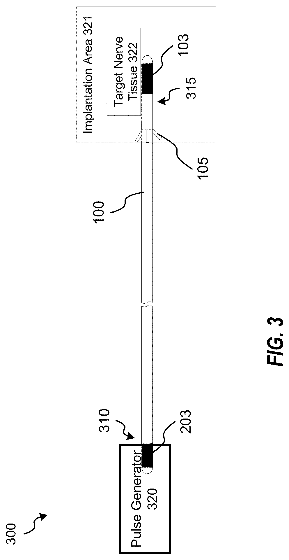
The present disclosure provides a stimulation lead for providing stimulation signals to nerve tissue and improved methods for constructing and manufacturing such a stimulation lead. The stimulation lead and/or methods includes a lead with a cable disposed within. At each end of the lead body a portion of the cable is exposed, and a metal ferrule is securely attached to the exposed cable portion. An electrode/contact is then securely attached to the metal ferrule such that the electrode covers the metal ferrule, a portion of the lead body, and a transition point where the exposed cable exits the lead body. A tine component may be swaged around a portion of the term end, configured to provide a retaining force against an force acting upon the stimulation lead, while allowing insertion of the stim end of the stimulation lead during implantation, and extraction of the stim end during explantation.

Description

CROSS-REFERENCE TO RELATED APPLICATION[0001]The present application claims the benefit of U.S. Provisional Patent Application No. 63 / 125,922 filed Dec. 15, 2020, and entitled “IMPLANTABLE PERIPHERAL NERVE STIMULATION LEAD,” the disclosure of which is incorporated by reference herein in its entirety.TECHNICAL FIELD[0002]The present disclosure relates generally to medical devices, and more particularly to a peripheral nerve stimulation lead.BACKGROUND[0003]Nerve stimulation has been shown to be helpful in treating patients with chronic intractable pain. For those patients who prove unresponsive to conservative pain management techniques, peripheral nerve stimulation (PNS) may be a successful therapy for pain management when the pain is known to result from a specific nerve. PNS is based in part on the Melzack-Wall gate control theory of pain. Sweet and Wespic first used electrical stimulation of peripheral nerves in the 1960s to mask the sensation of pain with a tingling sensation (pa...

Claims


Application Information

Patent Timeline
IPC IPC(8): A61N1/36A61N1/05A61N1/375
CPCA61N1/3606A61N1/36071A61N1/37518A61N1/0558
Inventor RAINES, AARON
Owner ADVANCED NEUROMODULATION SYST INC
Why Eureka
Try Eureka