Cover Having Wallet Feature for Electronic Devices

Inactive Publication Date: 2014-04-03
E MISHAN & SONS
View PDF4 Cites 22 Cited by
  • Summary
  • Abstract
  • Description
  • Claims
  • Application Information

AI Technical Summary

Benefits of technology

[0012]Another advantage of the invention is that it is simple to manufacture, and simple to adapt for use with different electronic devices or even with some prior art protective cases. For example, the same elastic band concept and attachment method can be used to add wallet functionality to any phone, or to add folder functionality to any tablet computer or electronic reader.
[0013]According to one aspect of the invention, a case for an electronic device having an added wallet or folder feature comprises a tray having a floor adapted to cover a rear surface of an electronic device in the tray, the floor having an outer surface, an inner surface, a plurality of ribs on the inner surface, and a perimeter. The tray also has a plurality of side walls connected to the perimeter of the floor and extending around some or all of the perimeter and adapted to cover respective sides of an electronic device in the tray. The floor includes at least one recess, the one or more recesses being defined by the ribs and the side walls. At least two spaced apart slots extend from recess through the floor.
[0014]A flexible elastic band extends over at least part of the outer surface of the floor between two slots, the band being for resiliently receiving items to be stored between the band and the outer surface of the floor.

Problems solved by technology

Although these devices are typically fragile and expensive, often including breakable components such as touch-sensitive display screens, many users carry them wherever they go.
Cases and covers are known for covering at least the backs and sides of electronic devices such as portable phones, smart phones, mobile phones, portable computing devices, portable digital data storage and playback devices, handheld personal electronic devices, digital media player devices, audio and video players, personal digital assistants, handheld wireless devices, handheld digital audi

Method used


Image

  • Cover Having Wallet Feature for Electronic Devices
  • Cover Having Wallet Feature for Electronic Devices
  • Cover Having Wallet Feature for Electronic Devices

Examples


Embodiment Construction

[0026]The thin protective cases having elastic bands for resiliently receiving items of present invention can easily be adapted for use with electronic devices of a variety of shapes and sizes, particularly devices that are relatively thin and flat. Example cases suited for smart phones are herein provided to illustrate the concept of invention, although the invention is not limited to phone cases.

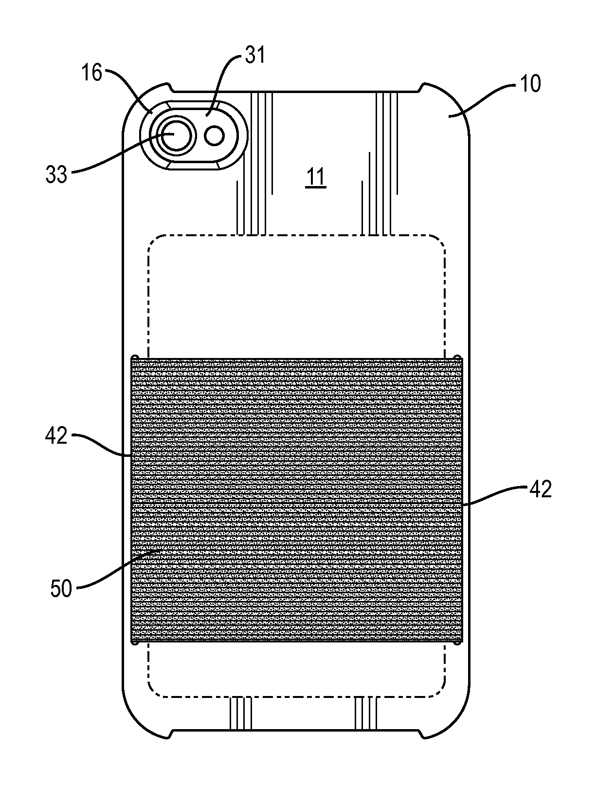
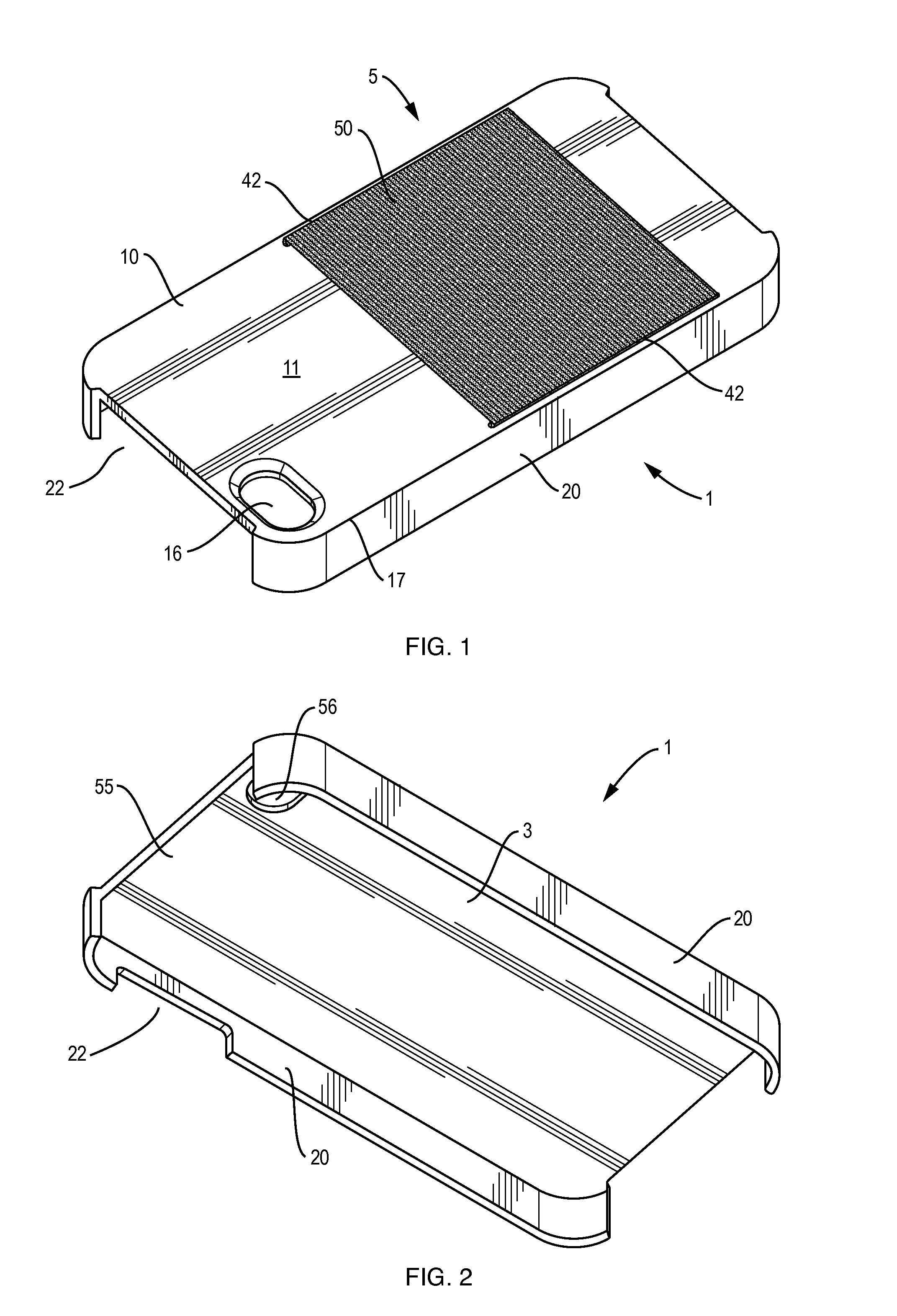
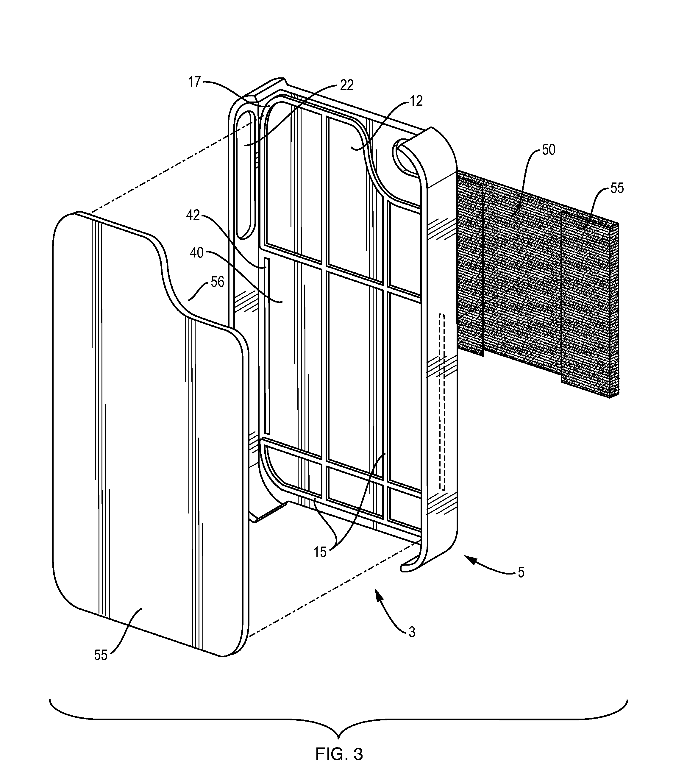
[0027]Referring now to the drawings, in which like reference numerals are used to refer to the same or similar elements, FIGS. 1-6 illustrate a case 1 for protecting a smart phone having a touch screen placed in a cavity 3 of the case.

[0028]The central component of the protective case 1 is a tray 5 having a back or floor 10 which has the approximate dimensions of a back surface 31 or other surface of an electronic device 30 to be held in the case. For example, the floor 10 of the tray 5 shown in FIGS. 1-2 and 7 has nearly the same dimensions as an Apple™ iPhone™, a type of “smart” internet...


PUM


Abstract

A safety cover for an electronic device has a tray with a floor, the floor having inner and outer surfaces, ribs on the inner surface, and side walls. The floor includes at least one recess and at least two spaced apart slots extending through the floor. A flexible elastic band extends over part of the outer surface of the tray floor which is between two slots. The band has two flaps, each extending through a slot into a recess and being adhered inside a recess to secure the elastic band. A cover plate covers the flaps inside the tray and provides a flat surface to engage the device. The elastic resiliently receives items to be held by the cover arrangement.

Description

FIELD AND BACKGROUND OF THE INVENTION[0001]The present invention relates generally to the field of electronic device protective cases, and, in particular, to a new and useful safely cover for electronic devices that includes a wallet or pocket feature having flexible dimensions so that the case will always have the thinnest possible cross-section.[0002]In recent years there has been a proliferation of portable electronic gadgets and devices such as portable MP3 players, smart phones, navigation devices, electronic readers, and touch-screen computers. Since the 1990's these devices have become common everyday items. Although these devices are typically fragile and expensive, often including breakable components such as touch-sensitive display screens, many users carry them wherever they go.[0003]Cases and covers are known for covering at least the backs and sides of electronic devices such as portable phones, smart phones, mobile phones, portable computing devices, portable digital d...

Claims


Application Information

Patent Timeline
IPC IPC(8): H05K5/02
CPCH05K5/02H04M1/185H04M1/21
Inventor MISHAN, DYLANEDGEMON, JENNA MARIELEE, STUART HARVEY
Owner E MISHAN & SONS
Why Eureka
Try Eureka