Electric power tool

Active Publication Date: 2006-06-22
HILTI AG
View PDF12 Cites 21 Cited by
  • Summary
  • Abstract
  • Description
  • Claims
  • Application Information

AI Technical Summary

Benefits of technology

[0011] It is the object of the invention to provide an electric power tool with an percussion mechanism which is simple to manufacture and with a fan elem

Problems solved by technology

The known solution is disadvantageous in that the additional housing shell is not always sufficiently robust for operation on a construction site and often has special design requirements.
There are also additional production costs.
This known solution is disadvantageous in that the percussion mech

Method used


Image

  • Electric power tool
  • Electric power tool
  • Electric power tool

Examples


Example

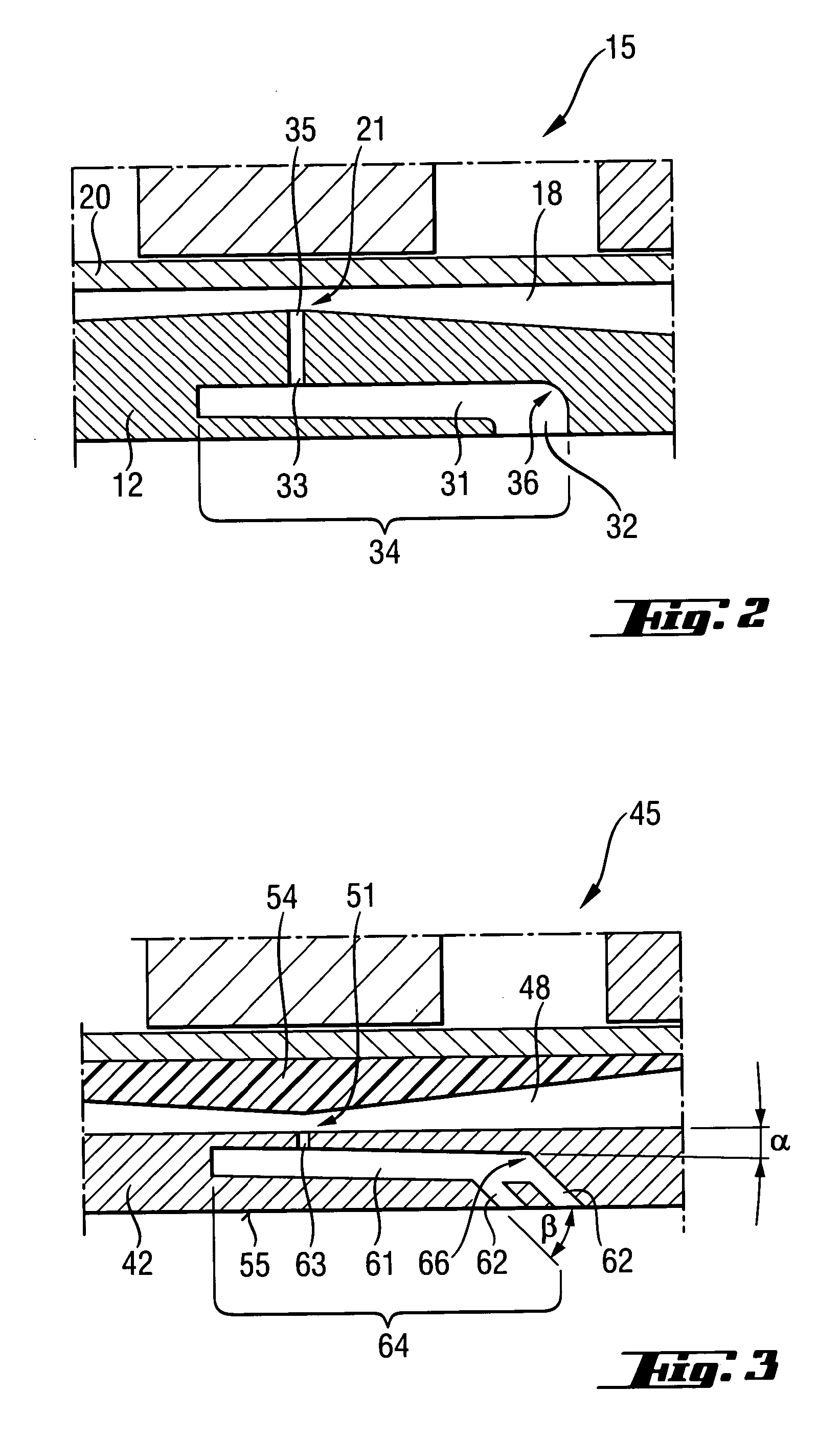
[0030] In the second embodiment example of the electric power tool, only separate sections of which are shown in FIG. 3, the percussion mechanism 45 is arranged at a distance from the external housing 42 in order to form cooling air channels 48 extending parallel to the longitudinal extent. An insertion element 54 is provided in every cooling air channel 48 for creating the constriction 51 of the cross-section of the cooling air channel 48.

[0031] Further, a fresh air channel 61 is associated with each cooling air channel 48. The fresh air channel 61 communicates with the atmosphere via two intake openings 62 in the external housing 42, on the one hand, and communicates with the cooling air channel 48 via a connection opening 63, on the other hand. The fresh air channel 61 has a portion 64 extending at an angle α to the longitudinal extension of the cooling air channel 48. In this embodiment example, the connection opening 63 also has a smaller cross-section than the sum of the cros...


PUM


Abstract

An electric power tool includes a percussion mechanism (15) located in an external housing (12) of the power tool (11) and driven by a driving motor (13) connected with the percussion mechanism (15) by a gear unit (14). An arrangement for cooling the power tool (11) includes a fan element (19) located in the external housing for generating a cooling air flow (26), a cooling air channel (18) extending along a longitudinal extent of the percussion mechanism (15) and a cross-section of which has a constriction (21; 51), a fresh air channel (31; 61) having an intake opening (32; 62) for communicating with atmosphere and formed in the external housing (12; 42) and a connection opening (33; 63) for communicating with the cooling air channel (18; 48) and arranged in an area of the constriction (21: 51) of the cooling air channel (18; 48).

Description

BACKGROUND OF THE INVENTION [0001] 1. Field of the Invention [0002] The present invention relates to an electric power tool, particularly a chisel hammer, drill hammer or combination hammer, and including an external housing, a percussion mechanism arranged in the external housing, a motor for driving the percussion mechanism, a gear unit for connecting the driving motor with the percussion mechanism, and means for cooling the driving motor and the gear unit and including a fan element located in the external housing for generating a cooling air flow in the external housing, and a cooling air channel extending along a longitudinal extent of the percussion mechanism. [0003] 2. Description of the Prior Art [0004] When operating electric power tools of the type mentioned above, the driving motor, percussion mechanism, gear units, and any existing electronics, as heat-generating components, generate heat that must be removed in order to prevent overheating of the electric power tool and...

Claims


Application Information

Patent Timeline
IPC IPC(8): B25D11/00
CPCB25D17/20B25D2211/003B25D2211/068B25D2217/0061B25F5/008
Inventor HAMMERSTINGL, STEFANRUNAU, BERND
Owner HILTI AG
Why Eureka
Try Eureka