Temperature compensated wire-conducting tube and method of manufacture

Inactive Publication Date: 2000-08-29
QUICK CONNECTORS
View PDF37 Cites 22 Cited by
  • Summary
  • Abstract
  • Description
  • Claims
  • Application Information

AI Technical Summary

Benefits of technology

The present invention solves the above problems by providing a simple means by which a tubular member may be manufactured having the required electrical conductors disposed therein. In addition, the invention disposes the electrical conductors in a position wherein the conductors will remain in position as they elongate due to thermal expansion.
The invention utilizes a continuous flat strip of metal that is formed into a continuous tubular member with the edges of the strip being juxtaposed. The edges of the strip are then welded together to provide a fluid-tight tubular member. In addition, as the flat strip is formed into a tubular member, the electrical conductors are fed into the tube simultaneously with the forming of the tubular member. The invention provides a means by which the electrical conductors may be protected from the damaging heat of the welding operation. It is preferable to use alloy steel for forming the tubular member and a shielded arc welding techni

Problems solved by technology

This would be a complicated arrangement, particularly since it is necessary to feed the members through a wellhead lubricating system since the wells must actually be in production to obtain measurements.
While this is possible, it is normally not possible to feed the electrical conductors through the length of the tubular member required in well logging operations.
This is time consuming and would increase the probability of an ineffective electrical connection.
In addition to the problem of providing the tubular member with the electrical conductors disposed therein, there is also the problem in thermal injection wells of providing for temperature compensation between the different materials used for the electrical conductors and the tubular me

Method used


Image

  • Temperature compensated wire-conducting tube and method of manufacture
  • Temperature compensated wire-conducting tube and method of manufacture
  • Temperature compensated wire-conducting tube and method of manufacture

Examples


Embodiment Construction

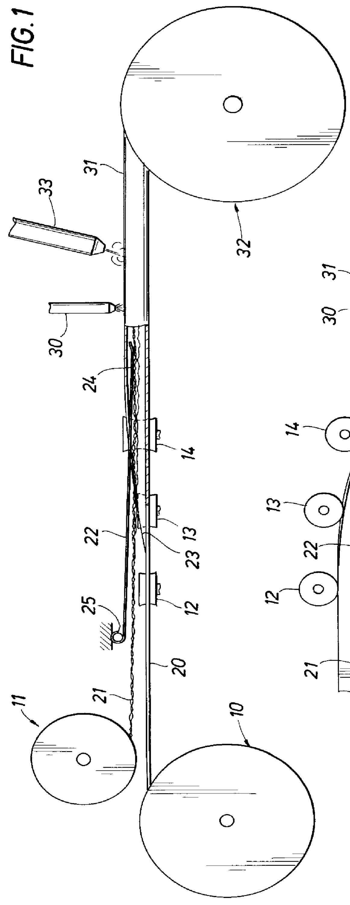
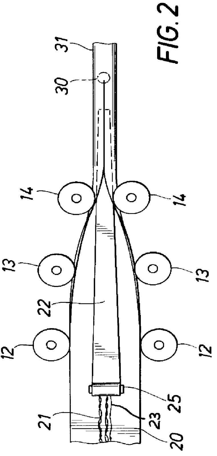
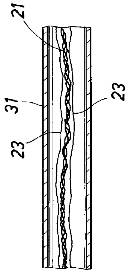
Referring now to FIGS. 1 and 2 there is shown a method and apparatus for continuously forming the tubular member and inserting the electrical conductors therein. In particular, there is shown two reels 10 and 11 for storing the required lengths of the strip material from which the tubular member is formed and the electrical conductors. While any desired material may be used for forming the tubular member, it is preferred that it be a corrosion-resistant material having relatively high strength at the elevated temperatures encountered in thermal injection wells. A suitable material is a stainless steel sold under the trade name of INCOLOY 8250.RTM., a tradename of International Nickel Company, Inc. The electrical conductors are shown as comprising two three-wire twisted assemblies 21 plug five single wires 23. Only one of two three-wire conductors and two of the single conductors are shown in FIGS. 3 and 4 for clarity. The strip material 20 is fed through a series of rollers 12, 13 a...


PUM

PropertyMeasurementUnit
Thicknessaaaaaaaaaa
Thicknessaaaaaaaaaa
Angleaaaaaaaaaa

Abstract

A method and apparatus for manufacturing a continuous metal tube having a plurality of electrical conductors disposed therein, by using a spring member to depress the electrical conductors while a flat metal strip is formed into a tubular member and welded to enclose the electrical conductors. The spring member functions to protect the electrical conductors from heat damage. The welding occurs completely downstream of the spring member in order to avoid excessive heat buildup in the spring member.

Description

BACKGROUND OF THE INVENTIONThe present invention relates to an elongated tubular member having electrical conductors disposed therein. The tubular member is capable of transmitting both a fluid medium and electrical power to a remote location. The term elongated is used to refer to tubular members of at least 1000 ft. or more in length with the members being fluid-tight sothat the fluid can be transmitted to the remote location.The tubular members of the present invention are particularly useful in the steam quality measuring systems disclosed in U.S. Pat. Nos. 4,581,926 and 4,736,627. These patents disclose methods and apparatus for measuring the quality of steam being injected into a subterranean formation to enhance the recovery of heavy crude deposits from the formation. Steam is the most widely used thermal recovery method where it is desirable to heat heavy crude deposits to more efficiently produce them. The patents require both the transmission of electrical power to the mea...

Claims


Application Information

Patent Timeline
IPC IPC(8): E21B17/20E21B17/00H01B13/00H01B13/004H01B7/16H01B13/26
CPCE21B17/206H01B7/16H01B13/004H01B13/2633
Inventor MOORE, BOYD B.WICKS, III, MOYE
Owner QUICK CONNECTORS
Why Eureka
Try Eureka