Microarraying head and microarrayer

Active Publication Date: 2007-04-03
THK CO LTD
View PDF18 Cites 4 Cited by
  • Summary
  • Abstract
  • Description
  • Claims
  • Application Information

AI Technical Summary

Benefits of technology

[0030]According to the invention, the retaining units can be delivered between the first conveying unit and the second con

Problems solved by technology

The work of forming spots is however suspended during the work of cleansing and drying the head.
In addition, the time required for the work of cleansi

Method used


Image

  • Microarraying head and microarrayer
  • Microarraying head and microarrayer
  • Microarraying head and microarrayer

Examples


Embodiment Construction

[0053]Now, a description will be given in more detail of preferred embodiments of the invention with reference to the accompanying drawings.

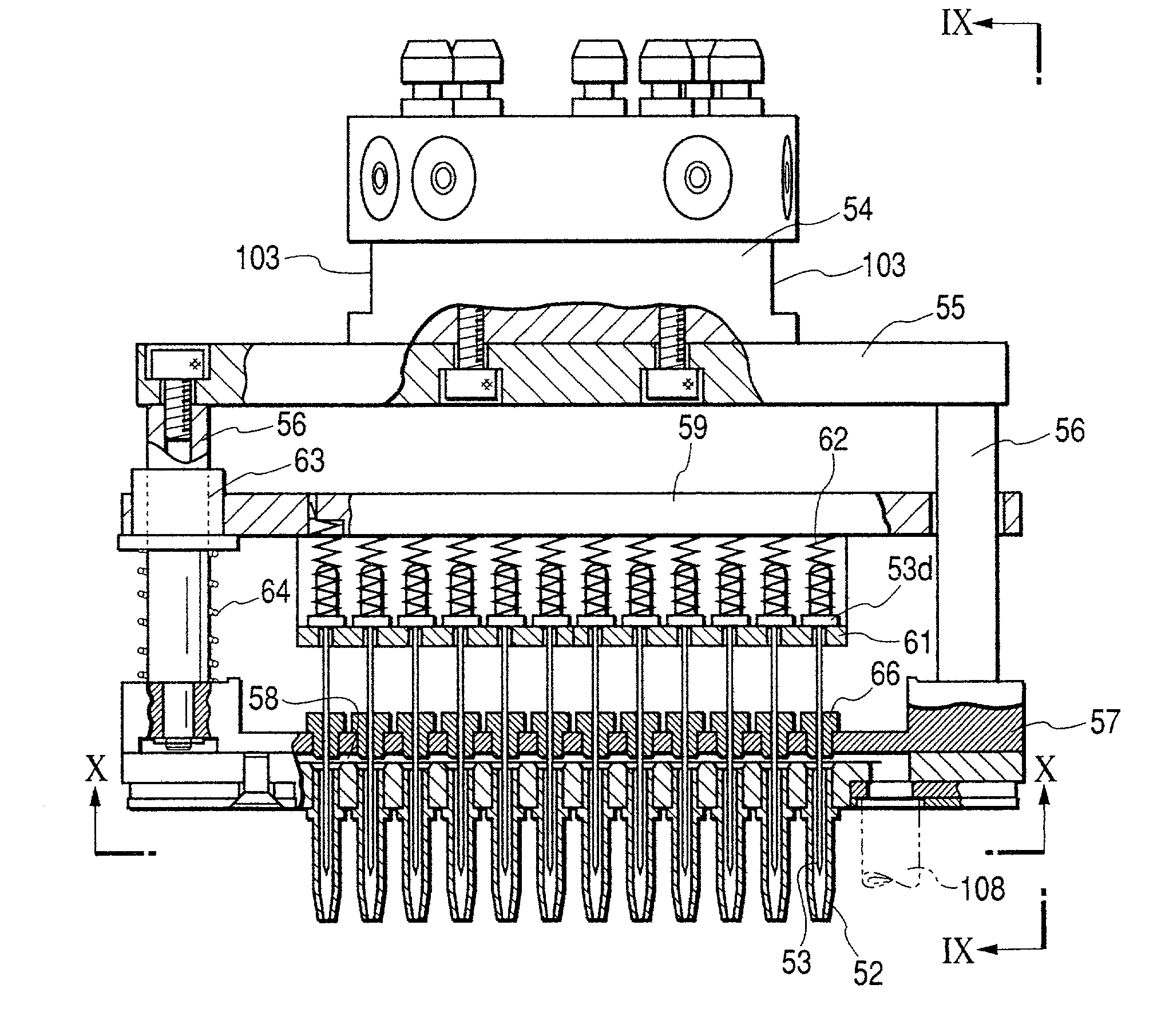
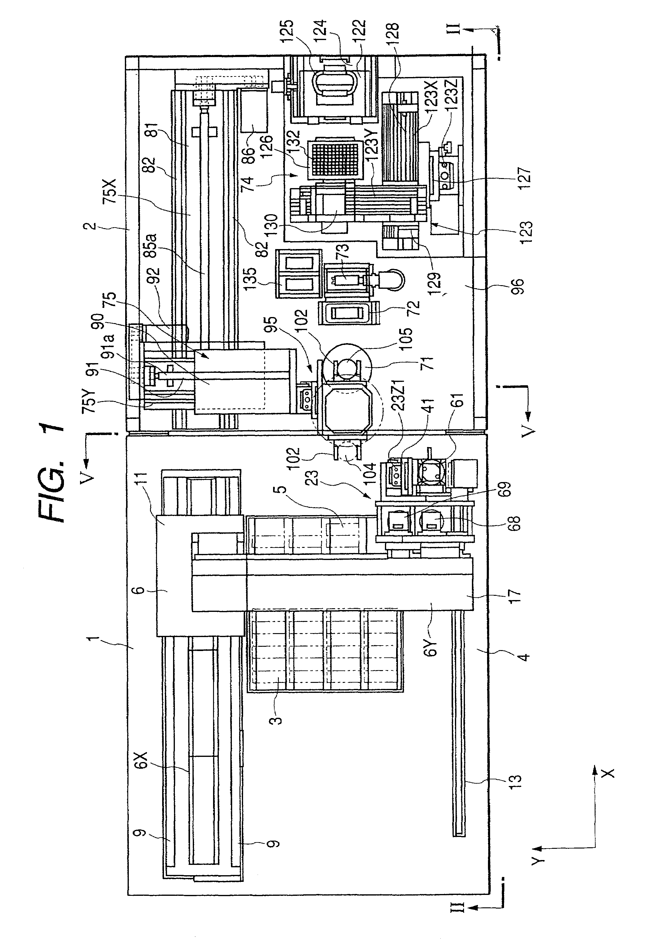
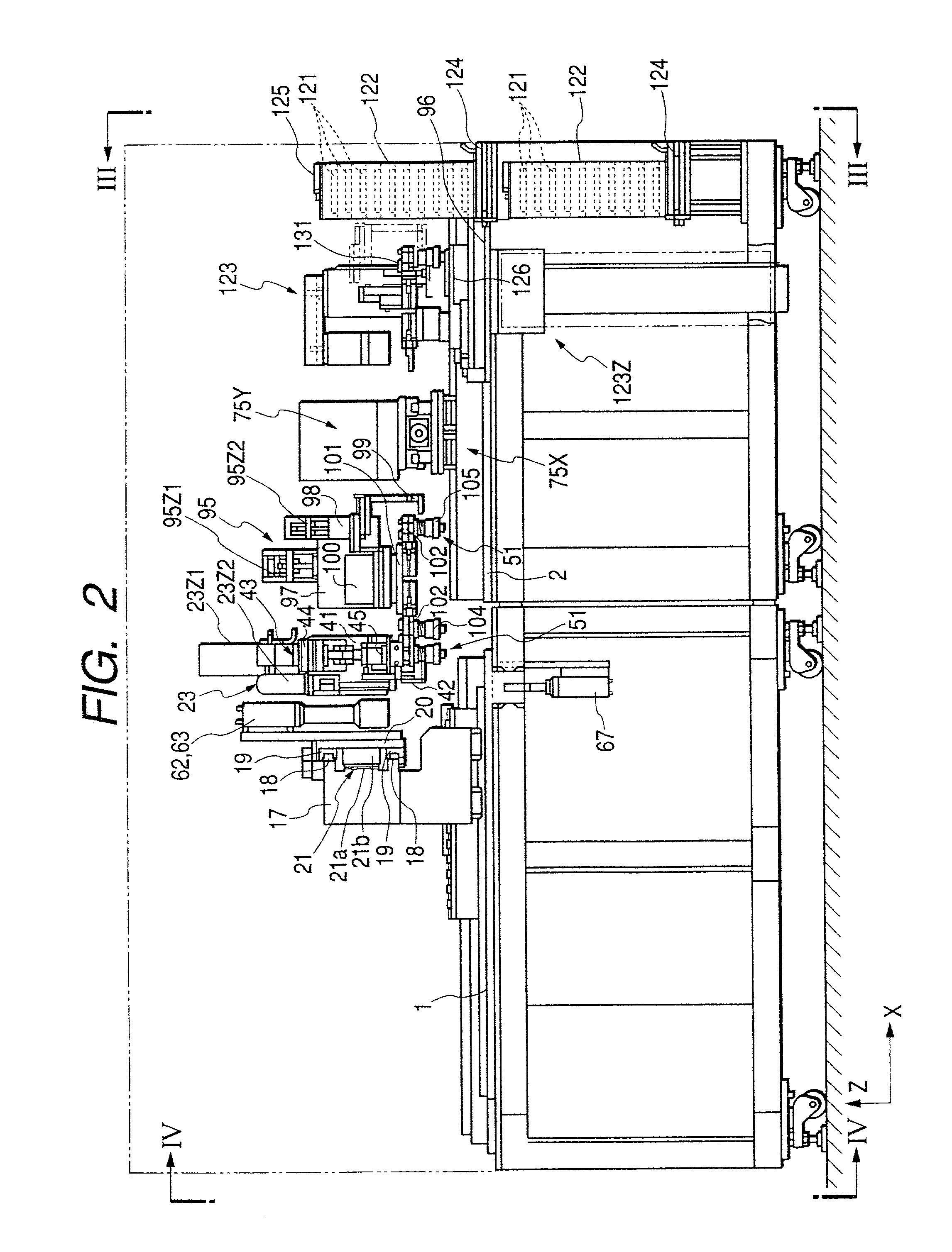
[0054]FIG. 1 is a plan view of the microarrayer according to this embodiment. FIG. 2 is a front view of this apparatus taken on line II—II in FIG. 1. FIG. 3 is a right side view of this apparatus, taken on line III—III in FIG. 2. FIG. 4 is a left side view of the apparatus, taken on line IV—IV in FIG. 2. FIG. 5 is a sectional view of the apparatus, taken on line V—V in FIG. 1.

[0055]By this apparatus, a large number of spots of a solution of biological samples such as DNA fragments or oligonucleotides adjusted in advance are sequenced on a substrate made of slide glass, silicon or the like. Each substrate generally measures 1 cm2 to several tens of cm2, and several thousands to several hundred thousands of spots of DNA fragments are sequenced in this area. For example, each of the spots has a diameter ranging from several tens of microns to sever...


PUM

PropertyMeasurementUnit
Pressureaaaaaaaaaa

Abstract

A microarraying head 51 has a base portion 57 and a plurality of needles 53. The needles 53 are arranged in parallel with one another on the base portion 57. The needles 53 place a solution on substrates 3 with the top ends of the needles 53 touching substrates 3. Then, the needles 53 retain the solution including biological samples and form spots of the solution on the substrates 3. A space 58 for supplying cleansing fluid or the like is provided in the base portion 57 so as to extend all over the plurality of needles 53. Since the plurality of needles 53 can be all cleansed with substantially uniform pressure applied thereto, all the plurality of needles 53 can cleansed surely in a short time.

Description

BACKGROUND OF THE INVENTION[0001]1. Field of the Invention[0002]The present invention relates to a microarrayer for sequencing a large number of biological samples such as DNA fragments or oligonucleotides on substrates.[0003]2. Description of the Related Art[0004]Currently, technological development for analyzing the whole gene functions of a wide variety of organisms is in progress. DNA microarrays (that is, DNA chips) are of a large number of spots including DNA fragments or the like sequenced on glass slides or silicon substrates. Such DNA microarrays are very effective in analyzing gene expressions, genetic mutations, genetic variations, and the like.[0005]Each substrate generally measures 1 cm2 to several tens of cm2, and several thousands to several hundred thousands of spots of DNA fragments are sequenced in this area. Each of the DNA fragments on the substrate is investigated with a fluorescent-labeled DNA complementary thereto. Fluorescence is generated when hybridization ...

Claims


Application Information

Patent Timeline
IPC IPC(8): B01L3/02G01N1/10B01J19/00B01L99/00C12Q1/68C40B60/14G01N35/10
CPCB01J19/0046B01L3/0244B01L3/0251B82Y30/00G01N35/1004B01L99/00Y10T436/2575B01J2219/00527B01J2219/00585B01J2219/0059B01J2219/00596B01J2219/00605B01J2219/00659B01J2219/00677B01J2219/00689B01J2219/00691C40B60/14G01N2035/1037B01J2219/00387B01L13/02G01N35/00029G01N2035/00237G01N2035/00158
Inventor NAKAZAWA, TOJIIIMURA, AKIHIRO
Owner THK CO LTD
Why Eureka
Try Eureka