Ring fixator

a fixator and ring technology, applied in the field of external fixator apparatus of the ring type, can solve the problems of heavy and expensive fixator apparatus construction, useless, bulky and awkward to manipulate,

Inactive Publication Date: 2007-06-05
ORTHOFIX SRL
View PDF5 Cites 50 Cited by
  • Summary
  • Abstract
  • Description
  • Claims
  • Application Information

AI Technical Summary

Benefits of technology

[0010]Such a problem has been solved by the provision of a fixator apparatus comprising at least one pair of rings, of which one is proximal and an other is distal, and at least one tie rod interconnecting the rings to each other, wherein said at least one rod is split into two rod sections connected together by a joint and said joint comprises a pivot mount having a predetermined axis for the angular displacement of the rod sections and comprises a slide mount according to a predetermined sliding direction for offsetting the rod sections.

Problems solved by technology

Such fixator apparatuses are of simple construction and are suitable for ready adjustment of the ring spacing, but are useless when the rings need to be mutually set for a greater manoeuvring freedom, e.g. when the inclination of the rings to each other needs to be changed.
The tie plates afford a wider adjustment of the mutual position of the rings, but are bulky and awkward to manipulate.
However, this arrangement results in the construction of a heavy and expensive fixator apparatus.
WO 97 / 30650 discloses an external fixator whose two rings are linked to one another by means of triplets of rod sections, wherein the rod sections of each triplet are connected together by two locking joints, which allow to modify the inclination of the rings to one another but does not enable to rotate the rings with respect to one another.
Moreover, the handling of such an apparatus is quite complicate due to the high number of joints to be locked.
The latter allows to translate or rotate the rings with respect to one another but does not permit to modify the inclination of the rings to one another.
This apparatus is quite complicate to manipulate due to the absence of any sliding joints.

Method used


Image

  • Ring fixator
  • Ring fixator
  • Ring fixator

Examples


Embodiment Construction

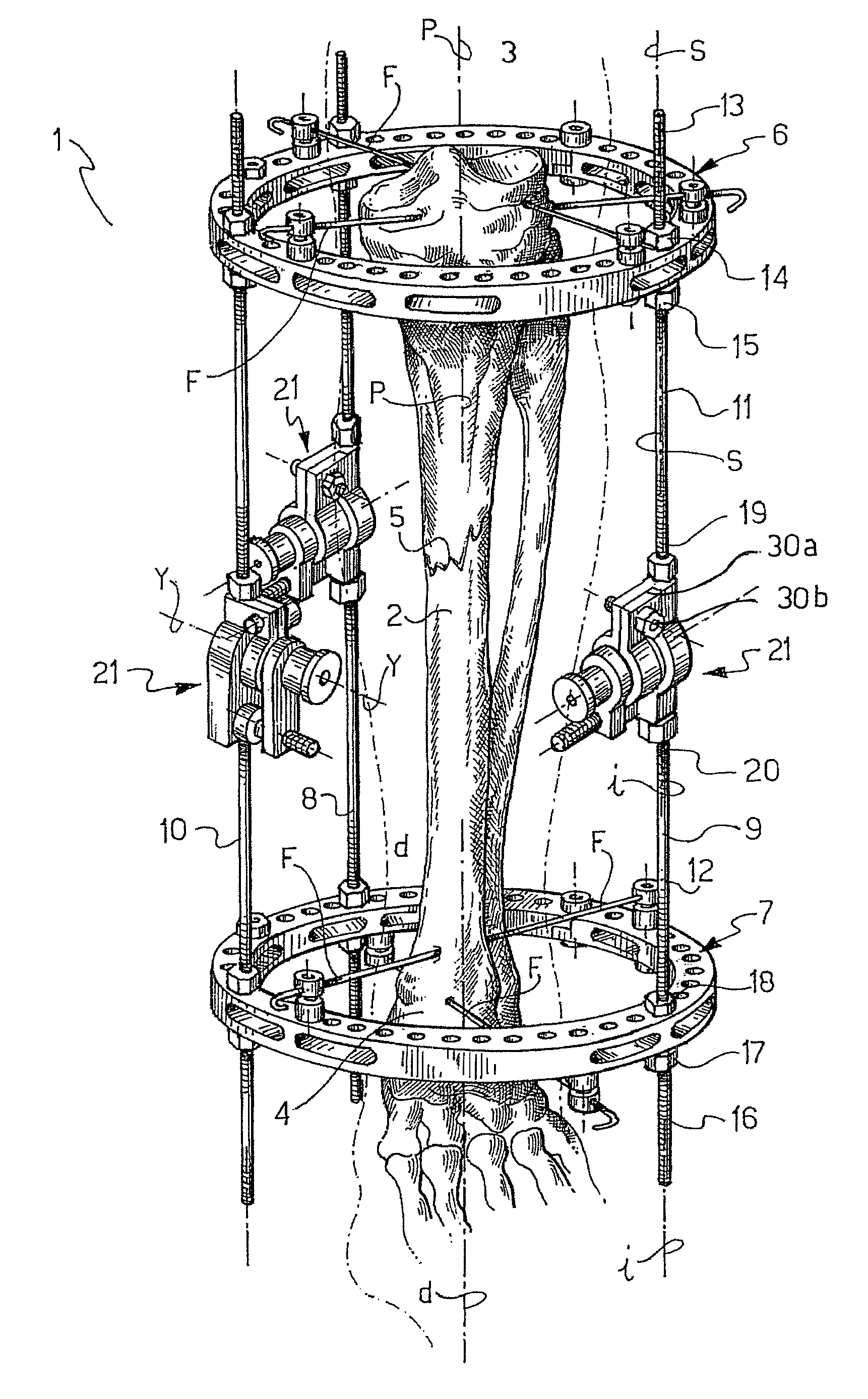
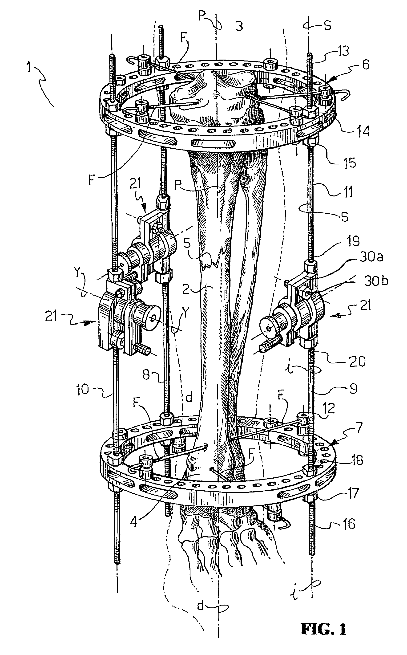
[0016]In the drawing views, a fixator device according to the invention is shown overall at 1, and is of the external ring type intended for stabilizing bone fractures.

[0017]In the example, the fixator apparatus 1 is applied to a tibia 2 having a proximal end 3, a distal end 4, and a middle portion including a brake 5.

[0018]The fixator 1 comprises a pair of rings, namely a proximal ring 6 and a distal ring 7, and comprises three tie rods 8, 9 and 10 connecting the rings 6 and 7 together.

[0019]The rings 6 and 7 are identical and circular in the example, and have a predetermined diameter. Their axes p—p and d—d, respectively, are coincident in a first condition of operation of the fixator apparatus, that is with the rings 6 and 7 exactly superposed on each other.

[0020]One end 3, 4 of the tibia 2 is secured to each ring 6, 7, respectively, by means of appropriate linking elements, in the form of wires F in the example.

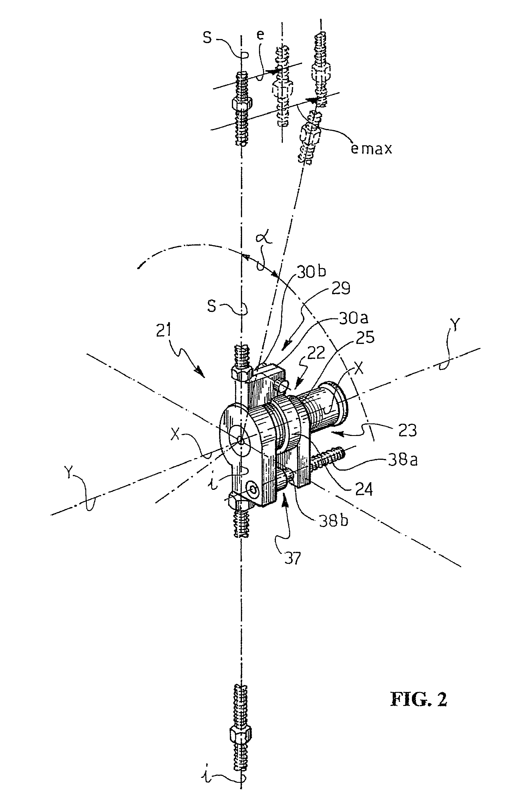
[0021]The tie rods 8, 9 and 10 are identical and essentially extend ...


PUM


Abstract

An external fixator apparatus (1) of the ring type for stabilizing bone fractures, including at least one pair of rings (6, 7), of which one (6) is proximal and the other (7) is distal, and at least one tie rod (8, 9, 10) interconnecting the rings (6, 7) to each other. The rod (8, 9, 10) is split into two rod sections (11, 12) connected together by a joint (21) and the joint (21) includes a pivot mount (22) having a predetermined axis (x—x) for the angular displacement of the rod sections (11, 12), and a sliding mount (23) according to a pre-determined sliding direction (y—y) for offsetting the rod sections (11, 12).

Description

FIELD OF THE INVENTION[0001]This invention broadly relates to an external fixator apparatus of the ring type for stabilizing bone fractures.[0002]In a particular embodiment, the invention provides a ring fixator apparatus of the type specified in the preamble of the main claim.[0003]As it is known, there is the necessity to set the mutual position of the rings, depending on the type of treatment to apply or on a particular fracture to stabilize.PRIOR ART[0004]A prior type of known ring fixator apparatuses currently in use comprises rings which are connected with each other by telescoping tie rods adapted to be extended as required. Such fixator apparatuses are of simple construction and are suitable for ready adjustment of the ring spacing, but are useless when the rings need to be mutually set for a greater manoeuvring freedom, e.g. when the inclination of the rings to each other needs to be changed.[0005]Also available are splint apparatuses wherein the rings are connected by the ...

Claims


Application Information

Patent Timeline
Patent Type & Authority Patents(United States)
IPC IPC(8): A61B17/00A61F4/00A61F5/04A61B17/62A61B17/60
CPCA61B17/62
Inventor VENTURINI, DANIELECOATI, MICHELEROSSI, GRAZIANO
Owner ORTHOFIX SRL
Why Eureka
Try Eureka