C-shaped disc prosthesis

a disc prosthesis and disc technology, applied in the field of spinal implants and methods, can solve the problems of changing the structure of the disc, the disc, the disc, etc., and the pain of patients, and the most anterior surgical approaches, however, tend to be more invasive than the posterior approach

Active Publication Date: 2007-08-28
DEPUY SPINE INC (US)
View PDF80 Cites 61 Cited by
  • Summary
  • Abstract
  • Description
  • Claims
  • Application Information

AI Technical Summary

Benefits of technology

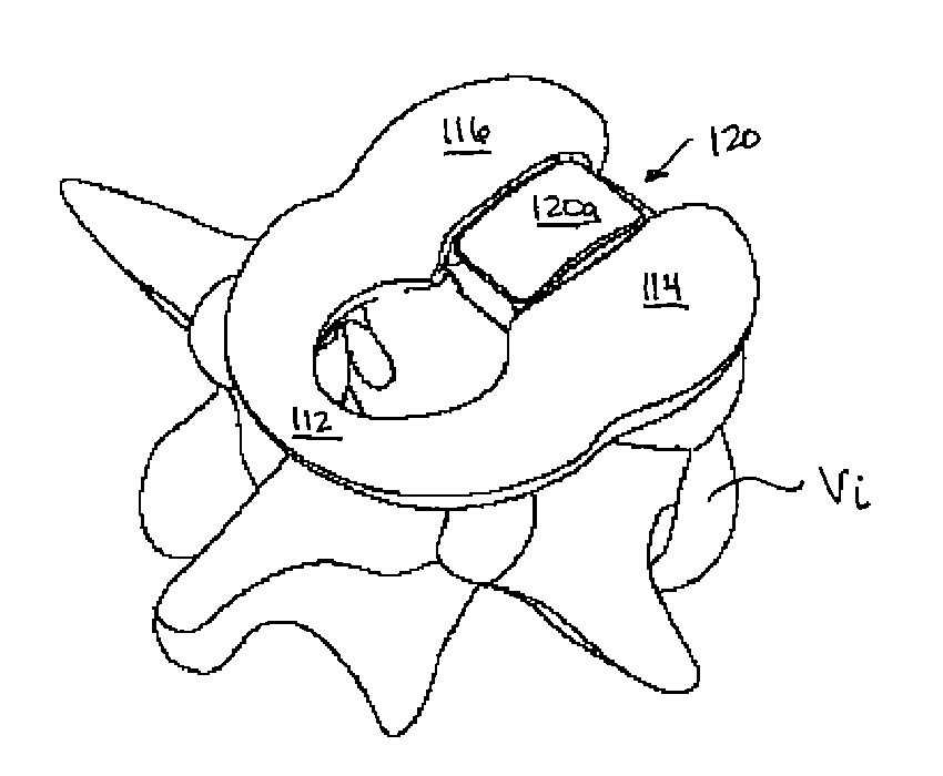
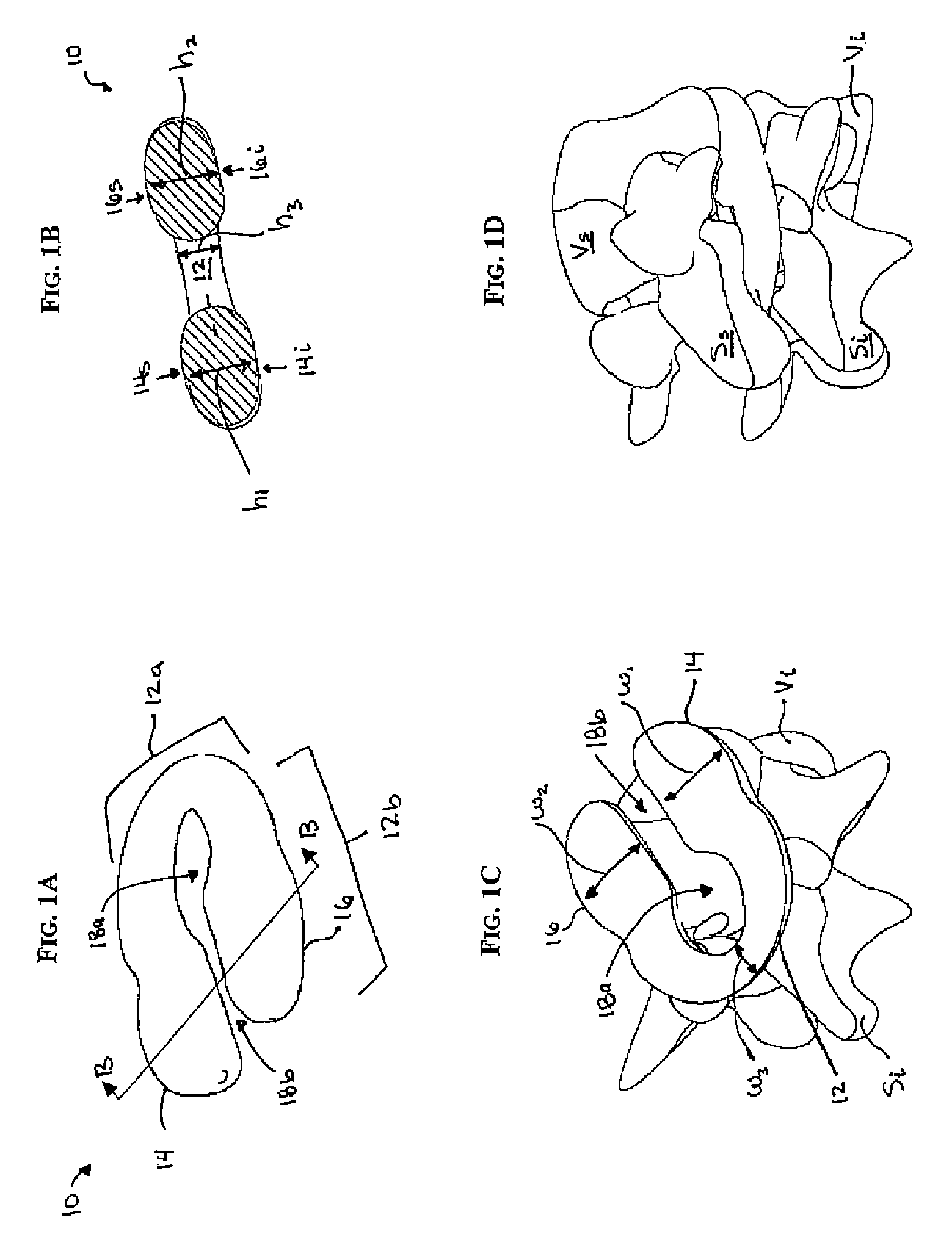
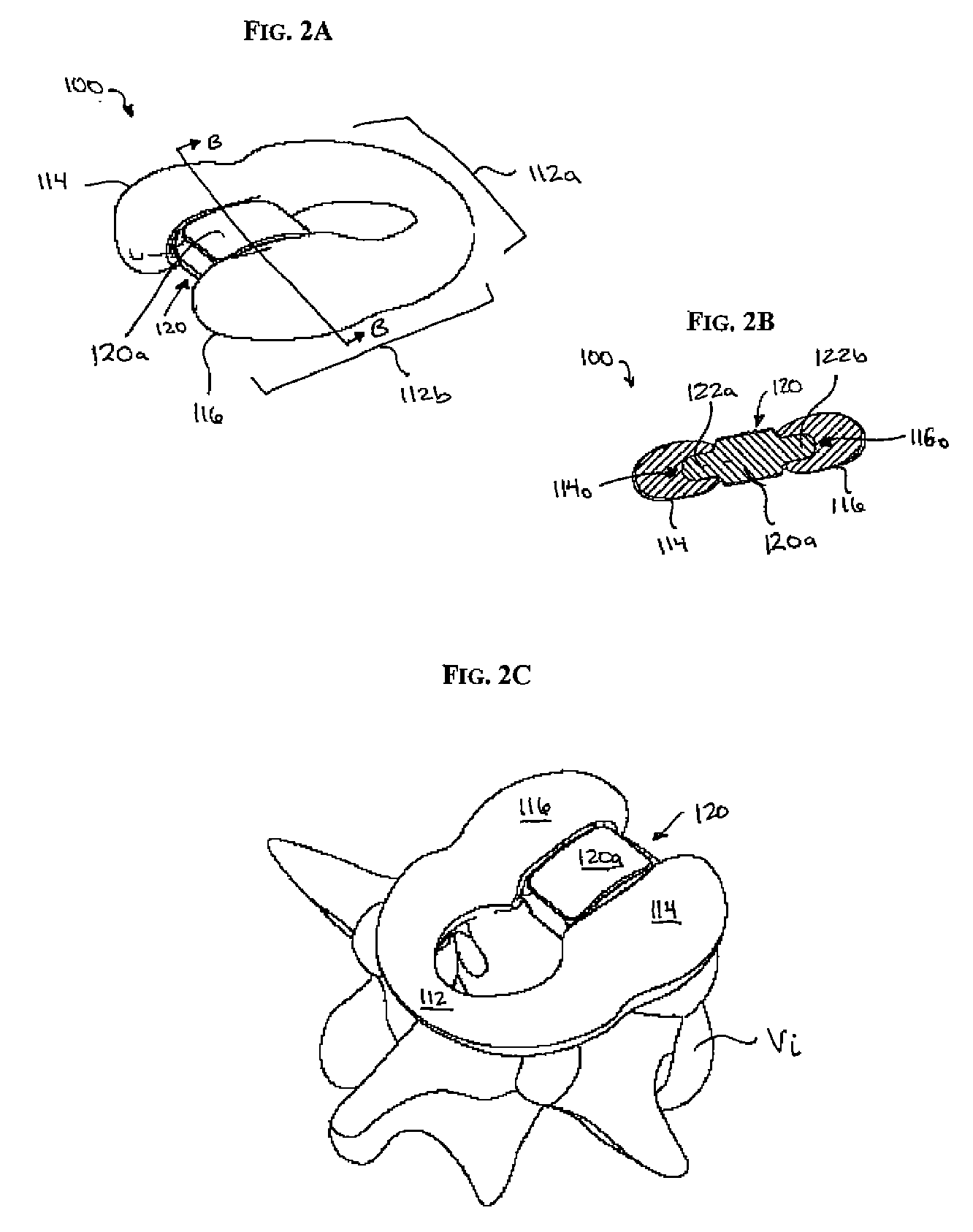
[0011]In yet another exemplary embodiment, a method for stabilizing adjacent vertebrae is provided and includes positioning a central member between adjacent vertebrae, positioning a posterior portion of an implant around a spinal cord, and positioning opposed arms of an anterior portion of the implant on opposed lateral sides of the central member. In one exemplary embodiment, the opposed arms of the anterior portion of the implant can be positioned on opposed lateral sides of the central member by sliding the opposed arms around the central member such that wing members extending from opposed lateral sides of the central member are received within openings formed in the opposed arms. In another exemplary embodiment, the central member can be implanted using a posterio-lateral approach, and the implant can be implanted using a posterior approach.

Problems solved by technology

Disease, advancing age, and trauma can lead to changes in various bones, discs, joints, and ligaments of the body.
This condition often results in chronic back pain, which can be anywhere from mild to severe.
Most anterior surgical approaches, however, tend to be more invasive than posterior approaches due to the nature and amount of the anatomy that needs to be displaced in order to successfully access the disc space.

Method used


Image

  • C-shaped disc prosthesis
  • C-shaped disc prosthesis
  • C-shaped disc prosthesis

Examples


Embodiment Construction

[0023]Certain exemplary embodiments will now be described to provide an overall understanding of the principles of the structure, function, manufacture, and use of the devices and methods disclosed herein. One or more examples of these embodiments are illustrated in the accompanying drawings. Those of ordinary skill in the art will understand that the devices and methods specifically described herein and illustrated in the accompanying drawings are non-limiting exemplary embodiments and that the scope of the present invention is defined solely by the claims. The features illustrated or described in connection with one exemplary embodiment may be combined with the features of other embodiments. Such modifications and variations are intended to be included within the scope of the present invention.

[0024]The present invention provides various methods and devices for repairing or replacing damaged, injured, diseased, or otherwise unhealthy intervertebral discs. In one exemplary embodime...


PUM

PropertyMeasurementUnit
heightaaaaaaaaaa
compressibleaaaaaaaaaa
movementaaaaaaaaaa

Abstract

Exemplary implants and methods are provided for stabilizing adjacent vertebrae. In one embodiment, an implant is provided having a shape that allows the implant to be positioned between adjacent vertebrae using a posterior approach while avoiding contact with the spinal cord. For example, the implant can include an anterior portion that is adapted to be positioned between adjacent vertebrae, and a posterior portion that is adapted to extend around a spinal cord. In certain exemplary embodiments, the implant can also be configured to allow motion between the adjacent vertebrae.

Description

CROSS REFERENCE TO RELATED APPLICATIONS[0001]The present invention claims priority to U.S. Provisional Application Ser. No. 60 / 584,055, filed on Jun. 30, 2004 and entitled “C-Disc,” which is hereby incorporated by reference in its entirety.FIELD OF THE INVENTION[0002]The present invention relates to spinal implants and methods.BACKGROUND OF THE INVENTION[0003]Disease, advancing age, and trauma can lead to changes in various bones, discs, joints, and ligaments of the body. Some changes and trauma often manifest themselves in the form of damage or degeneration to a spinal disc. This condition often results in chronic back pain, which can be anywhere from mild to severe. This pain can sometimes be eliminated by spinal fusion in which two adjacent vertebral bodies are jointed together after removing the intervening intervertebral disc. A prosthetic device is usually placed between the two adjacent vertebral bodies, in place of the removed disc, to fill the space left by the removed disc...

Claims


Application Information

Patent Timeline
Patent Type & Authority Patents(United States)
IPC IPC(8): A61F2/44
CPCA61F2/30767A61F2/441A61F2/442A61F2002/30121A61F2002/30123A61F2002/30131A61F2002/30242A61F2002/30563A61F2002/30841A61F2230/0013A61F2230/0071
Inventor CASEY, NIALL
Owner DEPUY SPINE INC (US)
Why Eureka
Try Eureka