Method and apparatus for using thermal imaging and augmented reality

a technology of augmented reality and thermal imaging, applied in the field of computer graphics, augmented reality, firefighting, first responder training, thermal imaging, etc., can solve the problem of limiting the utility of the siz

Inactive Publication Date: 2007-08-28
INFORMATION DECISION TECH
View PDF5 Cites 16 Cited by
  • Summary
  • Abstract
  • Description
  • Claims
  • Application Information

AI Technical Summary

Benefits of technology

[0006]This invention facilitates the blending of computer-generated (virtual) graphical elements (which represent real world objects) with the real-world view of the user as seen through a thermal imaging camera. The actual (operational) thermal imaging camera has been specially instrumented with a removable device, which can determine the position and orientation of the thermal imaging camera. Virtual (computer-generated) imagery, such as fire and smoke, can then be placed in an appropriate location and viewed through the thermal imaging camera display. Superimposing virtual imagery onto a real world scene (which may be static or changing) and presenting the combined image as the “replacement” for the real world image is known as Augmented Reality (AR). The location and properties of the computer-generated graphical elements are known and may be input via a human or other means. The user's real world scene / image might consist of scenery that the user can normally see.
[0007]The user may visualize the combined virtual and real image using the traditional thermal imaging camera display, or in another embodiment of the invention, the user may view the combined image through a Self-Contained Breathing Apparatus (SCBA), possibly with a simulated thermal camera as the source image of the real world (most easily accomplished with a standard TV camera, and processing the image). In any case, a thermal representation of the real image (e.g., an office space with cabinets and desks) will be shown, overlaid with computer-generated graphical elements drawn to simulate their appearance as if they were really being observed by a thermal camera. The net result is an augmented reality. The invention includes use of a motorized camera to achieve tracking for augmented reality. The invention includes the user wearing most or all of the invention equipment, permitting the user to be self-contained.

Problems solved by technology

While it has the advantage of being able to detect translational motion in addition to orientation, its size limits its utility.

Method used


Image

  • Method and apparatus for using thermal imaging and augmented reality
  • Method and apparatus for using thermal imaging and augmented reality
  • Method and apparatus for using thermal imaging and augmented reality

Examples


Embodiment Construction

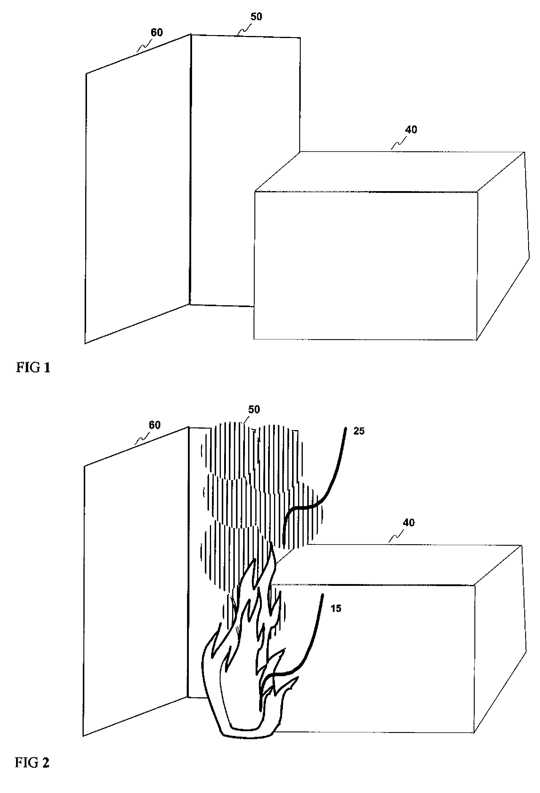
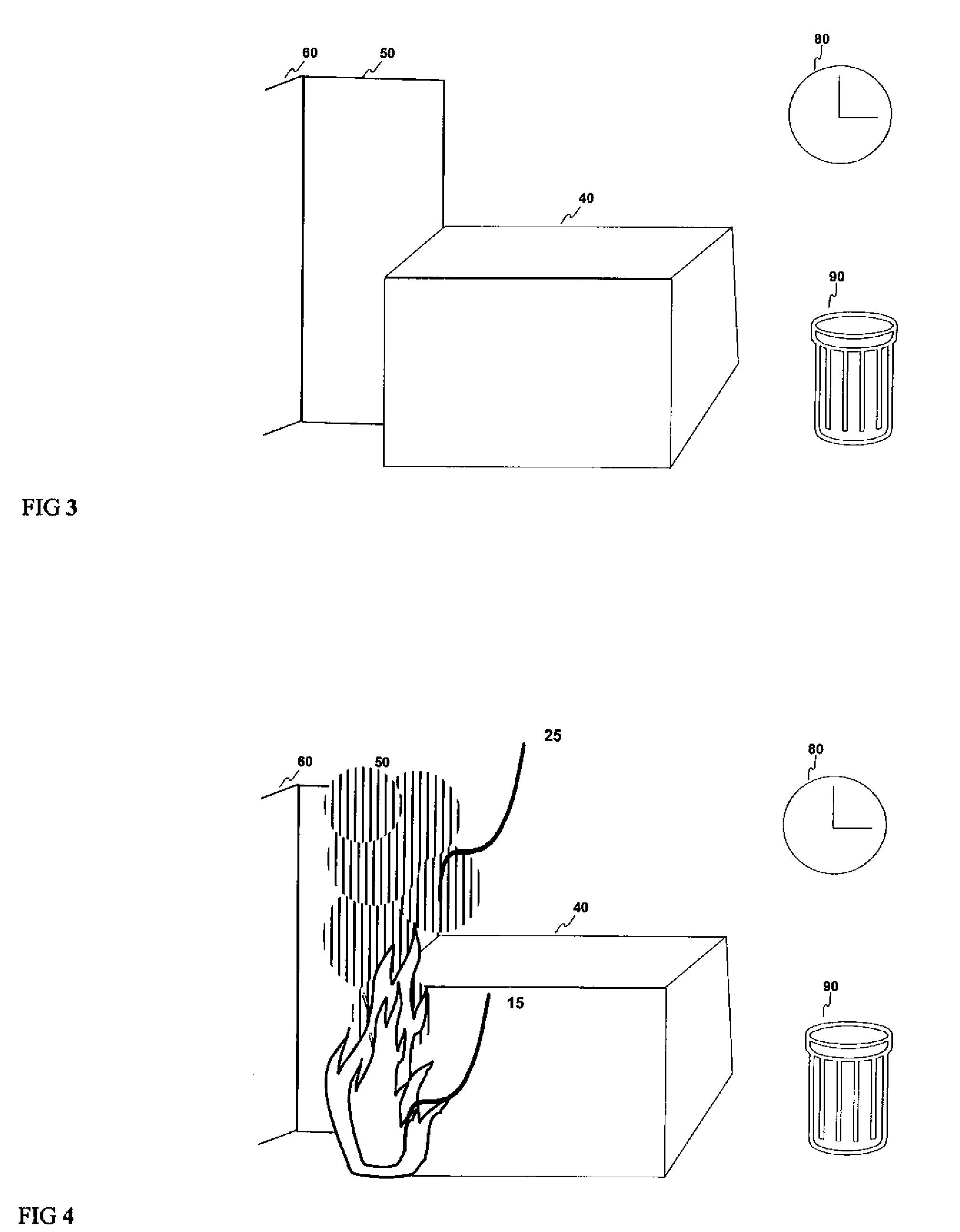
[0021]In the preferred embodiment of the invention, an image is acquired with an actual (operational) thermal imaging camera (such as the ISG Talisman K-90XL or the ISG K-1000). FIG. 1 represents an image captured from a thermal imaging camera that contains the view of an office, including multiple walls 50 and 60 and a desk 40. The captured image is then processed and displayed by the apparatus of the invention with a thermal view of the real scene augmented with a simulated thermal view of the fire and smoke injected into the scene, along with any applicable extinguishing agent (for example, water or foam). FIG. 2 shows the completed augmented view of FIG. 1, with simulated fire 15 and smoke 25. Since the fire and smoke are hot, they will appear as bright white in the thermal image. Additionally, most types of smoke are either completely or mostly transparent or translucent to thermal imaging cameras, and would be displayed accordingly.

[0022]The simulated fire 15 and smoke 25 rema...


PUM


Abstract

A method for using Augmented Reality (AR), in conjunction with a real or simulated thermal imager. A primary application is to train emergency first responders. Particularly, the system uses a thermal imaging camera or standard video camera, and tracking system to provide a tracked viewpoint in an AR environment. The augmented portions of the environment can consist of fire, smoke, extinguishing agent, or other emergencies. This allows for inexpensive, flexible, and realistic on-site training of fire fighting, damage control, search and rescue, and other first responder techniques using thermal imaging.

Description

CROSS REFERENCE TO RELATED APPLICATIONS[0001]This application claims priority of Provisional patent application 60 / 681,746 filed May 17, 2005; “Method and Apparatus for Training with Thermal Imaging and Augmented Reality.” This application is a continuation in part of patent application Ser. No. 11 / 092,083, filed on Mar. 29, 2005 now U.S. Pat. No. 7,046,214; “Method and System for Accomplishing a Scalable, Multi-User, Extended Range, Distributed, Augmented Reality Environment.” This application is a continuation in part of patent application Ser. No. 11 / 092,007, filed on Mar. 29, 2005 now U.S. Pat. No. 7,071,898; “Method for Using a Wireless Motorized Camera Mount for Tracking in Augmented Reality.” This application is a continuation in part of patent application Ser. No. 09 / 927,043, filed on Aug. 9, 2001 now U.S. Pat. No. 7,110,013; “Augmented Reality Display Integrated with Self-Contained Breathing Apparatus.” This application is a continuation in part of patent application Ser. N...

Claims


Application Information

Patent Timeline
Patent Type & Authority Patents(United States)
IPC IPC(8): G09G5/00
CPCG09B19/00
Inventor EBERSOLE, JOHN FRANKLINHOBGOOD, ANDREW WESLEYEBERSOLE, JR., JOHN FRANKLIN
Owner INFORMATION DECISION TECH
Why Eureka
Try Eureka