
Corrugated clothes hanger structure
a clothes hanger and corrugated technology, applied in the field of clothes hangers, can solve problems such as serious bodily harm, and achieve the effect of convenient production and low production cos
- Summary
- Abstract
- Description
- Claims
- Application Information
AI Technical Summary
Benefits of technology
Problems solved by technology
Method used
Image

Examples
Embodiment Construction
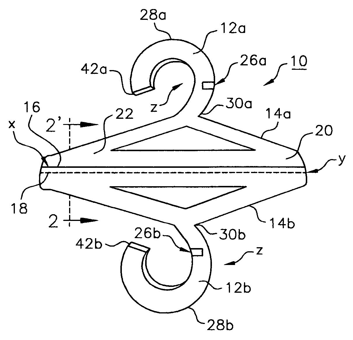
[0027]Referring to FIG. 1 there is shown a double clothes hanger shaped member 10 having a first slotted hook 12a and a second slotted hook 12b. Connected to the slotted hook 12a is a triangular shaped first shoulder body 14a. At the base of the body 14a there is a mirror image triangular shaped second shoulder body 14b. Near the base of the body 14a there is a first score 16 used as a fold line X. Near the base of the body 14b there is a second score 18 used as a fold line Y.
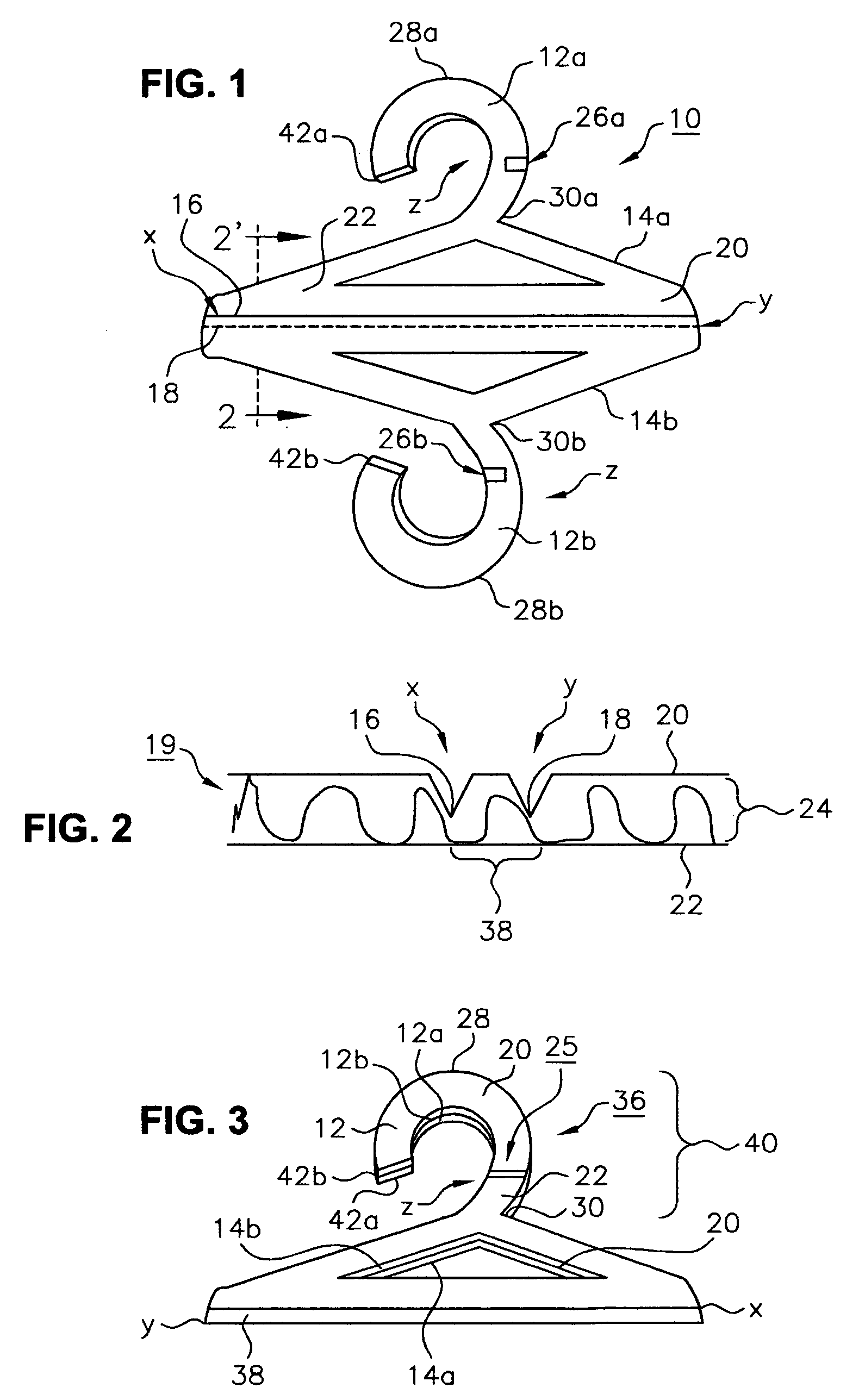
[0028]Referring to FIG. 2 there is shown a cross sectional view taken along the plane 2-2′ illustrated in FIG. 1. Shown is a section of a corrugated sheet member 19 preferably made of heavy-duty cardboard paper. The member 19 has a top sheet 20 and a bottom sheet 22 filled in between with corrugated filler 24. Further, there are shown cross-sections of the scores 16 and 18 used to form fold lines X and Y, respectively.
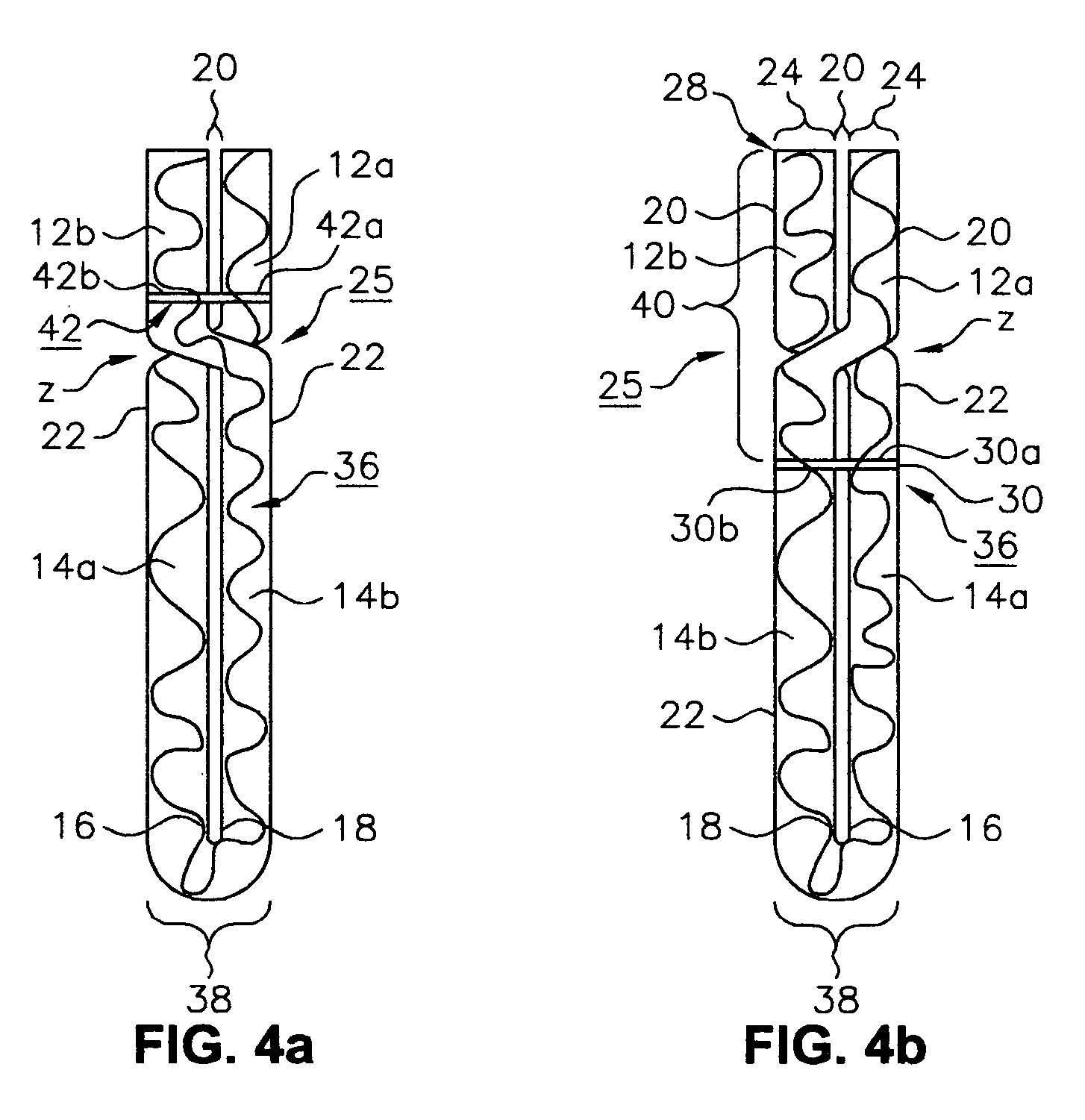
[0029]In FIG. 1 a novel cardboard paper clothes hanging instrument is formed from the slotted ...
PUM
| Property | Measurement | Unit |
|---|---|---|
| angle | aaaaa | aaaaa |
| perimeter | aaaaa | aaaaa |
| transparent | aaaaa | aaaaa |
Abstract
Description
Claims
Application Information