Methods of mounting a wind turbine, a wind turbine foundation and a wind turbine assembly

a technology of wind turbines and wind turbine components, which is applied in the direction of bulkheads/piles, underwater structures, artificial islands, etc., can solve the problems of lack of applicability and difficulty in mounting wind turbines, and achieve the effect of simplifying the packing of wind turbine components

Inactive Publication Date: 2007-10-16
VESTAS WIND SYST AS
View PDF11 Cites 25 Cited by
  • Summary
  • Abstract
  • Description
  • Claims
  • Application Information

AI Technical Summary

Benefits of technology

[0011]According to the invention, the foundation may be vibrated into the earth, thereby avoiding structure weakening hammering of foundation. Moreover, the upper part of the foundation, e.g. the flange, may be pre-fitted to the foundation structure, thereby minimizing the work on the site while attaching the tower to the foundation.
[0055]It should be noted, among other further advantages, that the invention facilitates a significant simplification of the work-process on-site, e.g. an offshore site where things are a little more complicated than they are on shore.

Problems solved by technology

It is well known that mounting of wind turbines has become a still more challenging exercise, incorporating both advanced logistic planning and up-front technical measures.
This is partly due to the fact that the overall dimensions of commercially attractive wind turbines has increased and e.g. partly to the fact that focus of mounting wind turbines are gradually shifted from traditional mounting locations to more extreme and difficult accessible areas, such as mountain areas and a offshore wind turbine parks.
This method may be advantageous for some purposes, but may lack applicability when dealing with large-scale wind turbines.

Method used


Image

  • Methods of mounting a wind turbine, a wind turbine foundation and a wind turbine assembly
  • Methods of mounting a wind turbine, a wind turbine foundation and a wind turbine assembly
  • Methods of mounting a wind turbine, a wind turbine foundation and a wind turbine assembly

Examples


Embodiment Construction

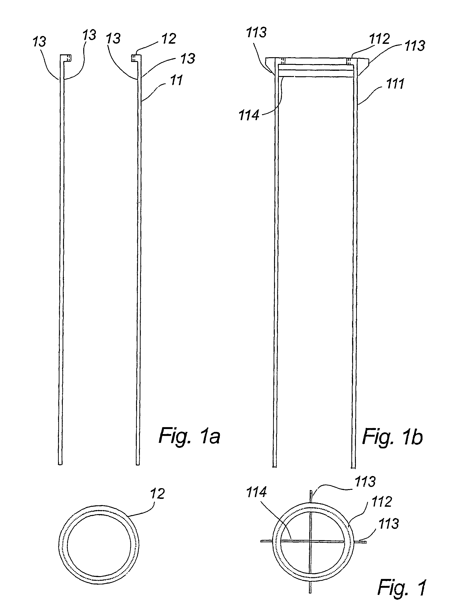
[0062]FIGS. 1a and 1b illustrates an offshore wind turbine foundation according to one preferred embodiment of the invention.

[0063]The illustrated offshore wind turbine foundation of FIG. 1a may be pre-manufactured onshore comprising both a main foundation body 11 and an upper attachment, here constituted by a flange 12.

[0064]Portions 13 of the wall of the illustrated mono pile may be applied as a gripping portion, to which a vibrator may be clamped, see FIG. 10a.

[0065]The illustrated structure, including the upper flange may be applied as a complete foundation, which may be positioned at a desired mounting site and subsequently serve as a foundation for e.g. a wind turbine tower, without performing further time consuming pre-processing between positioning if the foundation and the attachment of the tower to the foundation.

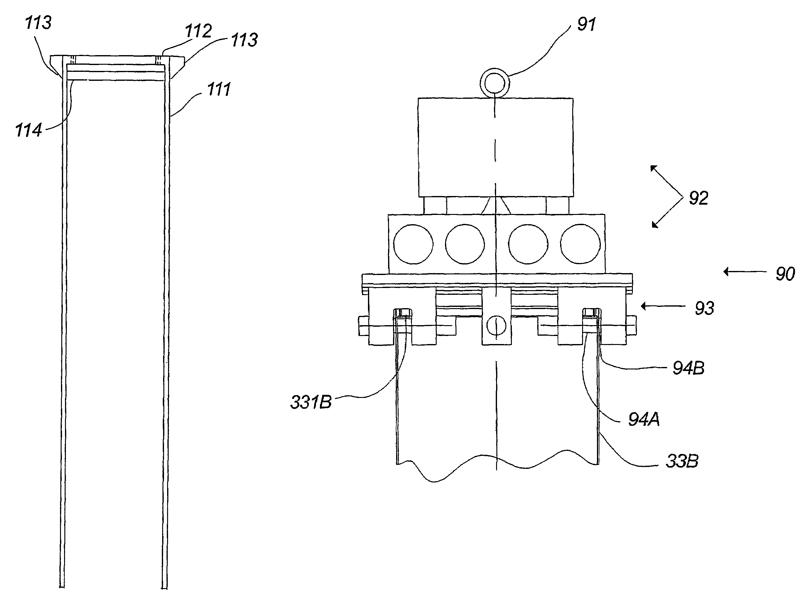
[0066]According to the illustrated embodiment of FIG. 1b a foundation body 111 has been pre-fitted with an additional vibration receiving interface in the form o...


PUM


Abstract

The invention relates to a method of mounting a wind turbine at a mounting location, said method comprising the steps of providing a foundation (33A, 33B), said foundation comprising a foundation body and pre-fitted upper attachment means vibrating at least a part of the foundation into the earth by transferring of vibrations into the structure of the foundation, mounting at least a part of said wind turbine to said upper attachment means (12) of said foundation. According to the invention, large scale wind turbines, especially offshore wind turbines, may be transported and mounted at the site in a cost-effective and expedient way.

Description

FIELD OF THE INVENTION[0001]The invention relates to a method of mounting a wind turbine at a mounting location as claimed in claim 1, a wind turbine foundation and a wind turbine assembly.BACKGROUND OF THE INVENTION[0002]It is well known that mounting of wind turbines has become a still more challenging exercise, incorporating both advanced logistic planning and up-front technical measures.[0003]This is partly due to the fact that the overall dimensions of commercially attractive wind turbines has increased and e.g. partly to the fact that focus of mounting wind turbines are gradually shifted from traditional mounting locations to more extreme and difficult accessible areas, such as mountain areas and a offshore wind turbine parks.[0004]One method dealing with mounting of offshore wind turbines has been disclosed in WO 99 / 43956, where foundation and the complete wind turbine are transported to the mounting location and mounted in one piece. This method may be advantageous for some ...

Claims


Application Information

Patent Timeline
Patent Type & Authority Patents(United States)
IPC IPC(8): F03D11/00B63B27/00E02B17/00E02D7/18E02D27/42E02D27/52F03D1/00F03D11/04
CPCE02B17/00E02D7/18E02D27/42B66C1/108F03D1/001F03D11/045E02D27/52E02B2017/0052E02B2017/0091F05B2230/6102Y02E10/728F03D13/22F03D13/10Y02E10/727Y02P70/50Y02E10/72
Inventor MORTENSEN, HENRIK KINDBERG
Owner VESTAS WIND SYST AS
Why Eureka
Try Eureka