Leg configuration for spring-mass legged locomotion

a legged locomotion and spring-mass technology, applied in the field of legged locomotion devices and methods, can solve the problems of affecting so as to achieve passive stability and improve the stability of the legged locomotion. the effect of stability

Active Publication Date: 2019-01-29
THE STATE OF OREGON ACTING BY & THROUGH THE OREGON STATE BOARD OF HIGHER EDUCATION ON BEHALF OF OREGON STATE UNIV
View PDF44 Cites 17 Cited by
  • Summary
  • Abstract
  • Description
  • Claims
  • Application Information

AI Technical Summary

Benefits of technology

[0014]By using physical springs in the current invention, ground reaction forces and impulses may not be controlled with the same fidelity as designs utilizing fully active controlled dynamics. Also, once passive dynamic components are physically fabricated (cut in metal), they cannot be changed like a software controller and thus are not as flexible. However, well-considered degree-of-freedom couplings and passive dynamics have the benefits of infinite bandwidth, minimization of internal work loops between actuators, and the potential for dimensional reduction and fewer actuators. In addition, the stability benefits of the spring-mass system are captured, and the self-stable nature of the behavior does not require high fidelity force control. Passive stability may also be influenced by the location of the center of mass relative to the kinematics of the robot or animal. A further advantage of the present invention is that it may include higher efficiency and power generation with smaller actuators, allowing lighter-weight machines for higher performance.
[0015]In yet a further aspect of the present invention, control ideas may be implemented in hardware to explicitly stabilize the passive dynamics mechanically. This concept is based on the idea that inherent stability can be improved through embedding certain control principles as mechanical coupling directly in the passive dynamics of the bipedal system. In one exemplary approach, the present invention may provide lateral stability in walking and running in a manner similar to that of a bicycle: primarily planar, with a lean-to-yaw coupling that imparts passive stability for upright balancing.
[0016]In a particular exemplary configuration of various aspects of the present invention, a robot for legged locomotion (incorporating passive dynamics) may be provided having a body and a leg having first, second, and third links. The first and second links may be pivotally mounted to one another, and the second and third links may be pivotally mounted to one another; the first link may have opposing first and second ends, with the first end pivotally mounted to the body. A first actuator and a first rotational element each may be mounted at the body; the first actuator and rotational element may be operably connected such that the first actuator is configured to rotate the first rotational element to rotate the first link about its first end. A second actuator and a second rotational element each may be mounted at the first link, and the second actuator and second rotational element may be operably connected such that the second actuator is configured to rotate the second rotational element to rotate the second link relative to the first link. The first and second actuators may be operable to swing the leg and extend / retract the first leg along a leg length direction. In addition, a transmission may be operably connected between the first and second rotational elements, and may be configured to transmit rotational movement of the first rotational element to the second rotational element. A first leg spring may be disposed in series between the first link and the third link, and a second leg spring disposed in series between the second actuator and second link. The leg springs may be configured to store energy therein during a first portion of a stance and configured to recover the stored energy during a second portion of the stance to provide passive dynamics for locomotion.
[0017]In addition, one or more gimbal actuators may be operably connected between the first link and the body. In particular, two gimbal actuators may be operably connected between the first link and the body, with the axis of rotation of each gimbal actuator oriented orthogonal to one another, so that one of the gimbal actuators controls yaw (to rotate the foot and steer the robot) and the other gimbal actuator controls adduction / abduction (to effect sideways balancing). Moreover, the axes of the two gimbal actuators each may be disposed orthogonal to an axis of rotation of the first actuator.

Problems solved by technology

Very high bandwidth, high power actuators, such as those in hydraulic machines, are sometimes capable of overcoming unfavorable passive dynamics and exhibiting highly dynamic behavior, but they do so at the cost of extremely high power requirements.
However, utilizing passive dynamics also constrains the behavior of the system to only those dynamics embodied by hardware, and cannot change without morphological changes.
As such, machines that focus exclusively or extensively on passive dynamics rather than computer control will have only a single behavior, such as a single gait at a single speed on flat ground, and may be very susceptible to disturbances such as small bumps in the ground.
However, there are several drawbacks: first, any motion takes the same amount of power regardless of the load placed on the actuator, because cylinder displacement results in fluid displacement from the high pressure side (pumped) of the system to the low pressure (collected) side of the system.
This effect can lead to very energetically wasteful motions if the actuators are moving without significant loading, such as during leg swing retraction.
Second, a hydraulic pump, hydraulic lines, and cylinders add significant complexity throughout a machine such as a legged robot.
While excellence in engineering makes it possible, fluid leaks and regular maintenance are common in existing state of the art systems.
The benefit of such a design choice is greater flexibility in gait development due to nearly direct computer control of leg dynamics, but the price is vastly wasteful energy use.
Thus, while the specialized hydraulic actuators are capable of this unnecessary challenge, there is an unavoidable cost of very low efficiency.

Method used


Image

  • Leg configuration for spring-mass legged locomotion
  • Leg configuration for spring-mass legged locomotion
  • Leg configuration for spring-mass legged locomotion

Examples


Embodiment Construction

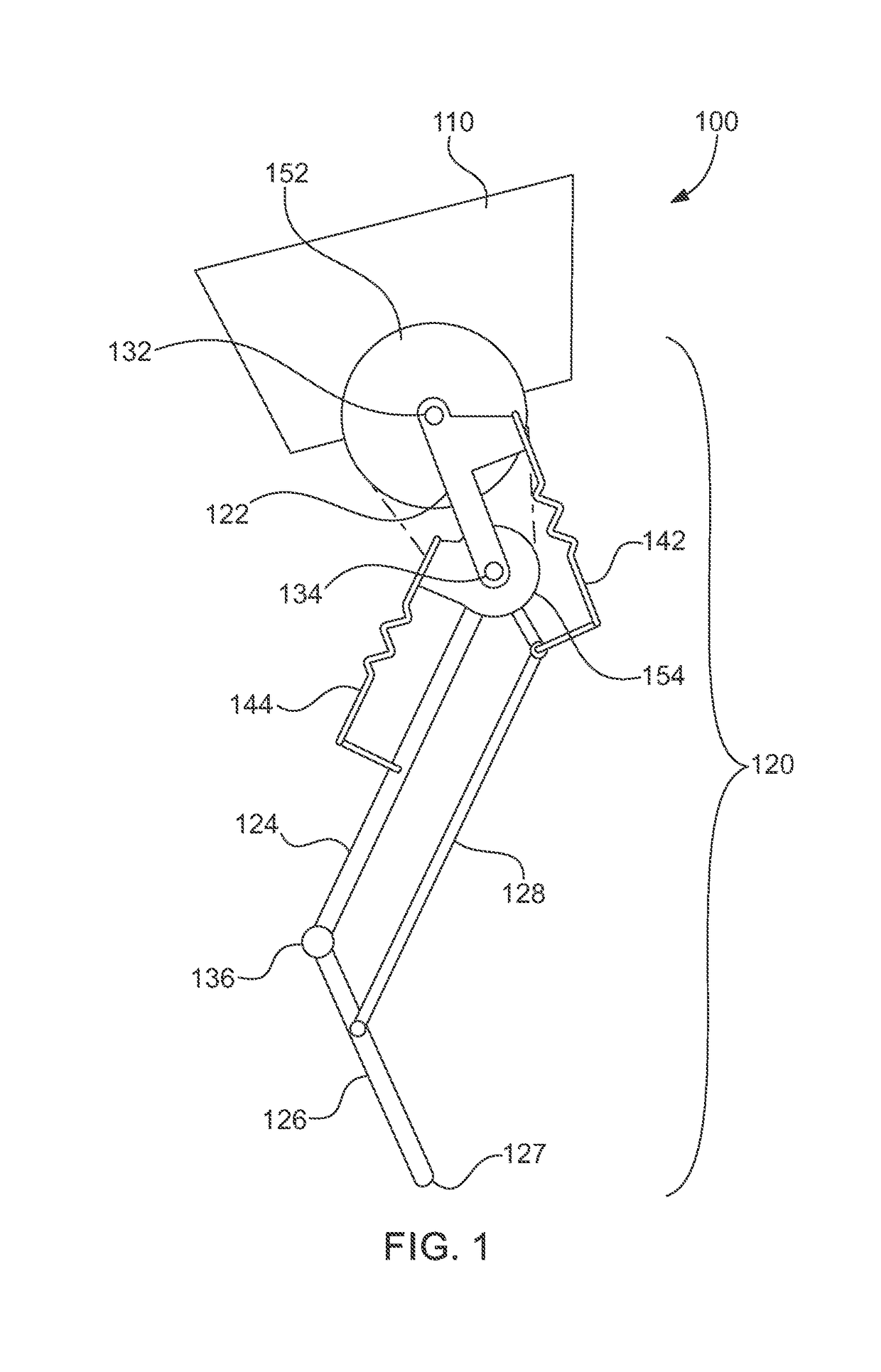
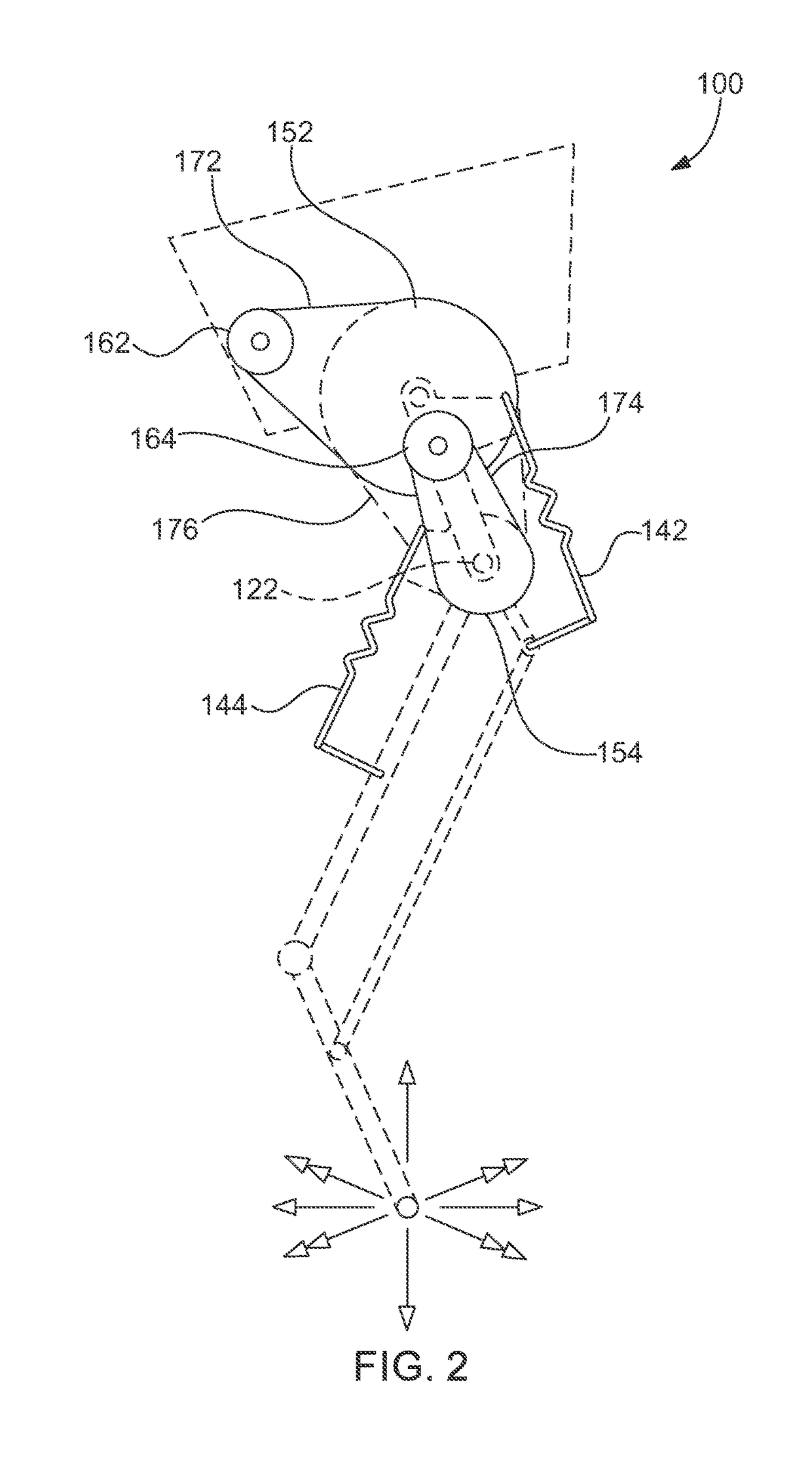
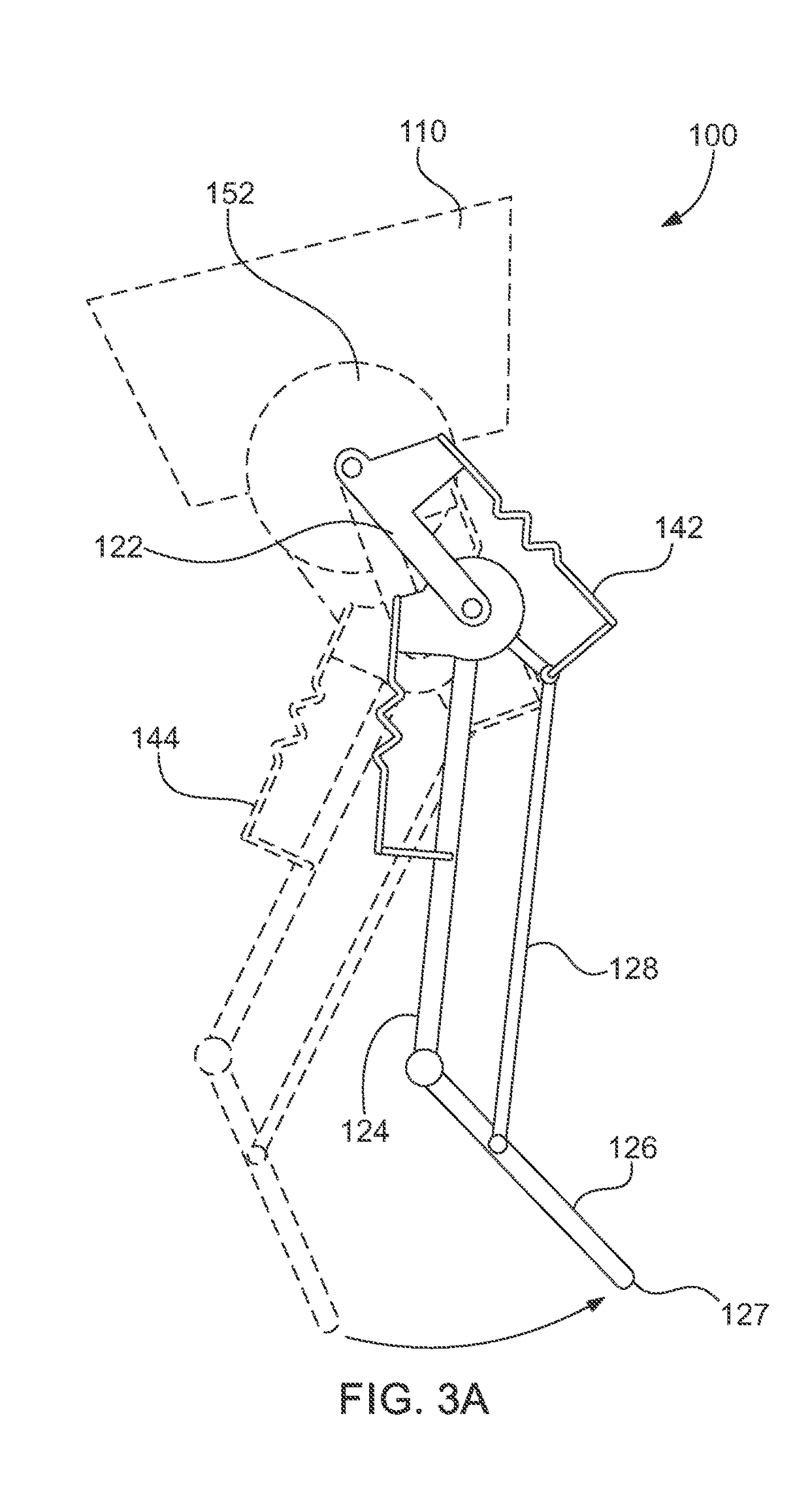
[0032]Referring now to the figures, wherein like elements are numbered alike throughout, FIGS. 1 and 2 schematically illustrate an exemplary robot 100 having an exemplary leg 120 for legged locomotion. One exemplary configuration of a robot of the present invention may include: a leg 120 comprising at least first, second, and third links 122, 124, 126, connected to each other by joints 134, 136 and to a body 110 by a joint 132; a first actuator 162 mounted on the robot body 110 to primarily control leg angle; a second actuator 164 disposed on the first link 122 used primarily to control leg length; the use of physical springs 142, 144 in the leg 120, in a literal approximation of a spring-mass model to create series elasticity between the distal two links 124, 126 and the actuators 162, 164 and the first link 122 and the second pulley 154; the use of mechanical transmissions 152, 154, such as pulleys, to constrain the motion of the at least three links 122, 124, 126 so they can be c...


PUM


Abstract

Devices and methods for legged locomotion, including a robotic leg for spring-mass legged locomotion incorporating passive dynamics.

Description

RELATED APPLICATIONS[0001]This application claims the benefit of priority of U.S. Provisional Application No. 62 / 167,953, filed on May 29, 2015, the entire contents of which application(s) are incorporated herein by reference.GOVERNMENT LICENSE RIGHTS[0002]This invention was made with government support under contract number W91CRB-11-1-0002 awarded by the Defense Advanced Research Projects Agency (DARPA). The government has certain rights in the invention.FIELD OF THE INVENTION[0003]The present invention relates generally to devices and methods for legged locomotion, including a robotic leg for spring-mass legged locomotion incorporating passive dynamics.BACKGROUND OF THE INVENTION[0004]Humans and other animals have the remarkable ability to negotiate an unknown and changing environment, not only without falling, but also with a level of efficiency currently unmatched in existing robotic systems. Literature suggests that a large portion of this agility may be due to the natural beh...

Claims


Application Information

Patent Timeline
Patent Type & Authority Patents(United States)
IPC IPC(8): B62D57/032B62D57/02
CPCB62D57/032B62D57/02Y10S901/01
Inventor HURST, JONATHANJONES, MIKHAIL SOBIEGRAJABATE, ANDREW MARTIN
Owner THE STATE OF OREGON ACTING BY & THROUGH THE OREGON STATE BOARD OF HIGHER EDUCATION ON BEHALF OF OREGON STATE UNIV
Why Eureka
Try Eureka