Reflective projection lens for EUV-photolithography

Inactive Publication Date: 2005-08-09
CARL ZEISS SMT GMBH
View PDF12 Cites 79 Cited by
  • Summary
  • Abstract
  • Description
  • Claims
  • Application Information

AI Technical Summary

Benefits of technology

[0014]It is one object of the invention to provide an EUV-projection lens operable at high numerical aperture that will allow largely correcting distortion errors along all image directions and providing sufficiently symmetric, high-intensity, illumination of the image fi

Problems solved by technology

The coatings are effectively “stuck onto” the uncoated substrates, which generally results in imaging performance that is much wors

Method used


Image

  • Reflective projection lens for EUV-photolithography
  • Reflective projection lens for EUV-photolithography
  • Reflective projection lens for EUV-photolithography

Examples


Example

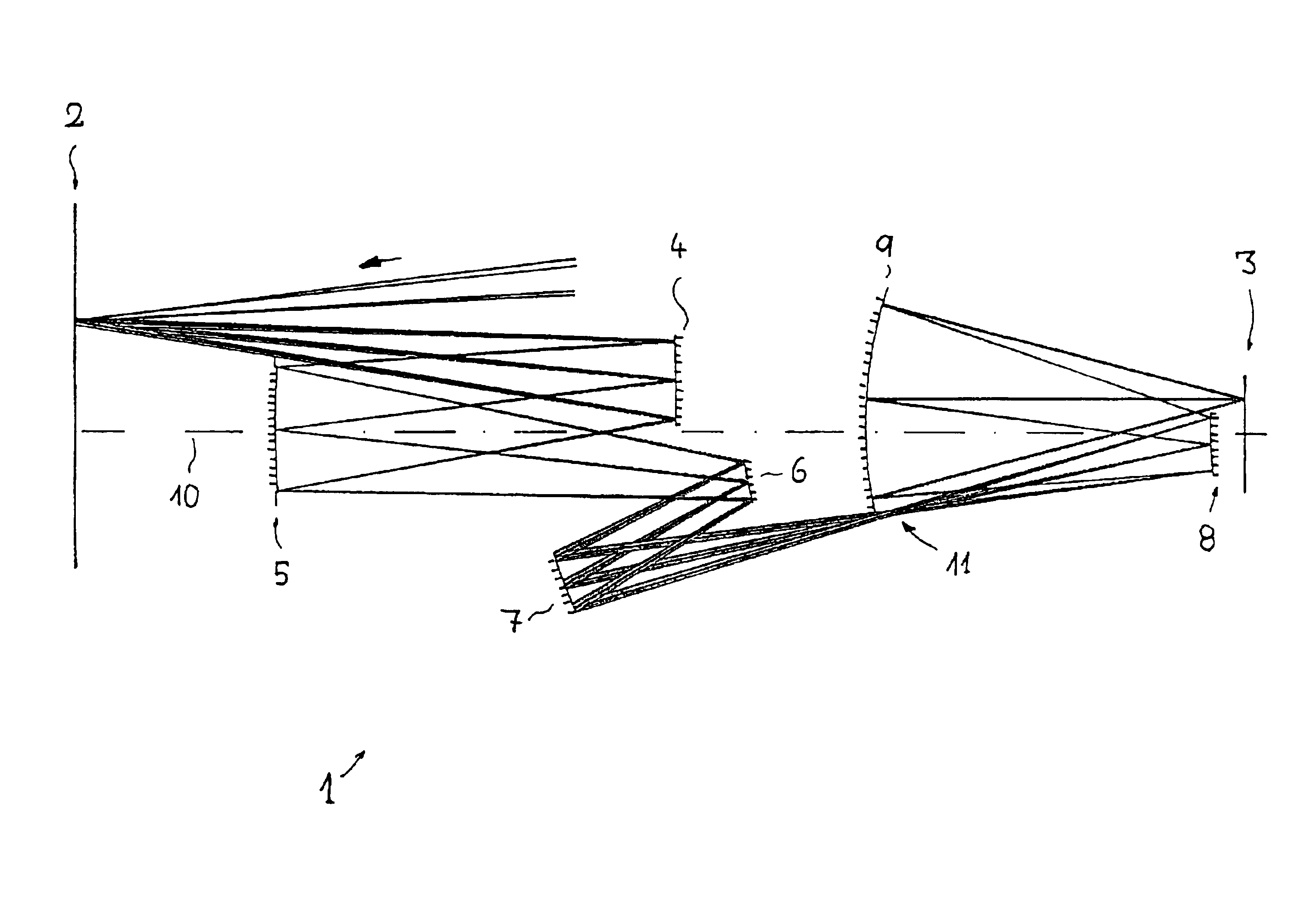
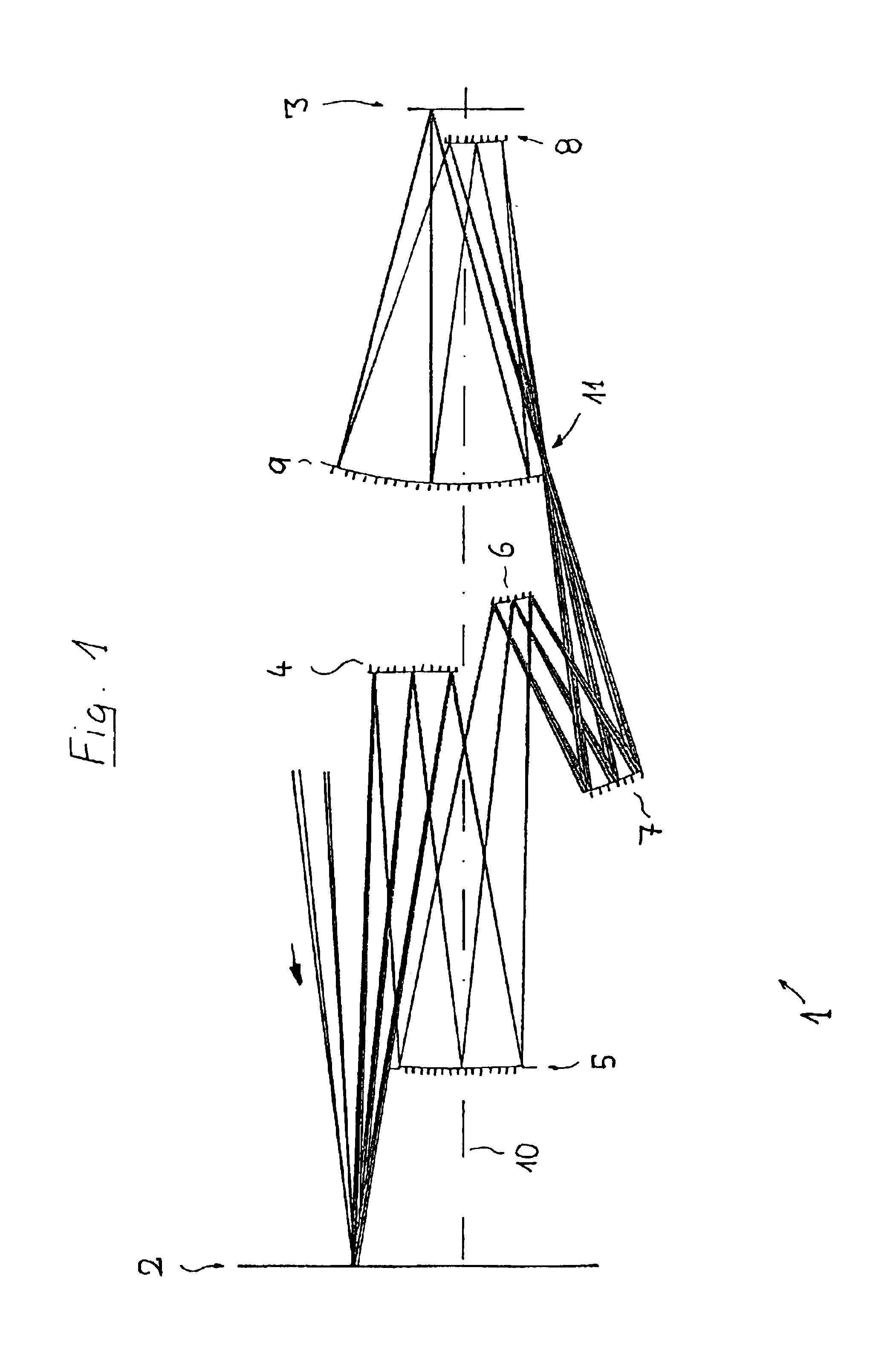
[0047]In the following description of the major principles of the invention, the term “optical axis” shall refer to a straight line or a sequence of straight-line segments passing through the paraxial centers of curvature of the optical elements involved, which, in the case of embodiments described here, consist exclusively of mirrors that have curved reflecting surfaces. In the case of those examples presented here, the object involved is a mask (reticle) bearing the pattern of an integrated circuit or some other pattern, such as a grating. In the case of those examples presented here, its image is projected onto a wafer coated with a layer of photoresist that serves as a substrate, although other types of substrate, such as components of liquid-crystal displays or substrates for optical gratings, may also be involved.

[0048]A typical layout of an EUV-projection lens 1 based on a preferred sample embodiment is shown in FIG. 1. It serves to project an image of a pattern on a reticle ...


PUM


Abstract

A projection lens for imaging a pattern arranged in an object plane onto an image plane using electromagnetic radiation from the extreme-ultraviolet (EUV) spectral region has several imaging mirrors between its object plane and image plane that define an optical axis of the projection lens and have reflective coatings. At least one of those mirrors has a graded reflective coating that has a film-thickness gradient that is rotationally symmetric with respect to a coating axis, where that coating axis is acentrically arranged with respect to the optical axis of the projection lens. Providing at least one acentric, graded, reflective coating allows designing projection lenses that allow highly uniform field illumination, combined with high total transmittance.

Description

[0001]The following disclosure is based on U.S. Provisional Application 60 / 308,861 filed on Aug. 1, 2001, which is incorporated into this application by reference and from which priority is claimed.BACKGROUND OF THE INVENTION[0002]1. Field of the Invention[0003]The invention relates to a projection lens for imaging a pattern arranged in an object plane onto an image plane employing electromagnetic radiation from the extreme-ultraviolet (EUV) spectral region.[0004]2. Description of the Related Art[0005]Projection lenses of that type are employed on projection exposure systems used for fabricating semiconductor devices and other types of microdevices and serve to project patterns on photomasks or reticles, which shall hereinafter be referred to using the generic terms “masks” or “reticles”, onto an object having a photosensitive coating at ultrahigh resolution.[0006]In order to allow creating even finer structures, various approaches to improving the resolving power of projection lens...

Claims


Application Information

Patent Timeline
IPC IPC(8): G02B17/06G02B17/00G03F7/20G02B27/18H01L21/027
CPCG02B5/0891G02B5/10G02B17/0657G03F7/70233G03F7/70958
Inventor MANN, HANS-JUERGENULRICH, WILHELMHUDYMA, RUSSELL M.
Owner CARL ZEISS SMT GMBH
Why Eureka
Try Eureka