Power supply circuit and power supply control method

Active Publication Date: 2013-09-19
NEC CORP
View PDF2 Cites 4 Cited by
  • Summary
  • Abstract
  • Description
  • Claims
  • Application Information

AI Technical Summary

Benefits of technology

[0025]According to the present invention, in a power supply circuit which uses a switching amplifier in combination with a linear amplifier, it becomes possible to correct errors of op

Problems solved by technology

However, each power supply circuit disclosed in non-patent document 1 and non-patent document 2 has problems respectively.
The power supply circuit 103 of non-patent document 1 shown in FIG. 6 has a prob

Method used


Image

  • Power supply circuit and power supply control method
  • Power supply circuit and power supply control method
  • Power supply circuit and power supply control method

Examples


first exemplary embodiment

The First Exemplary Embodiment

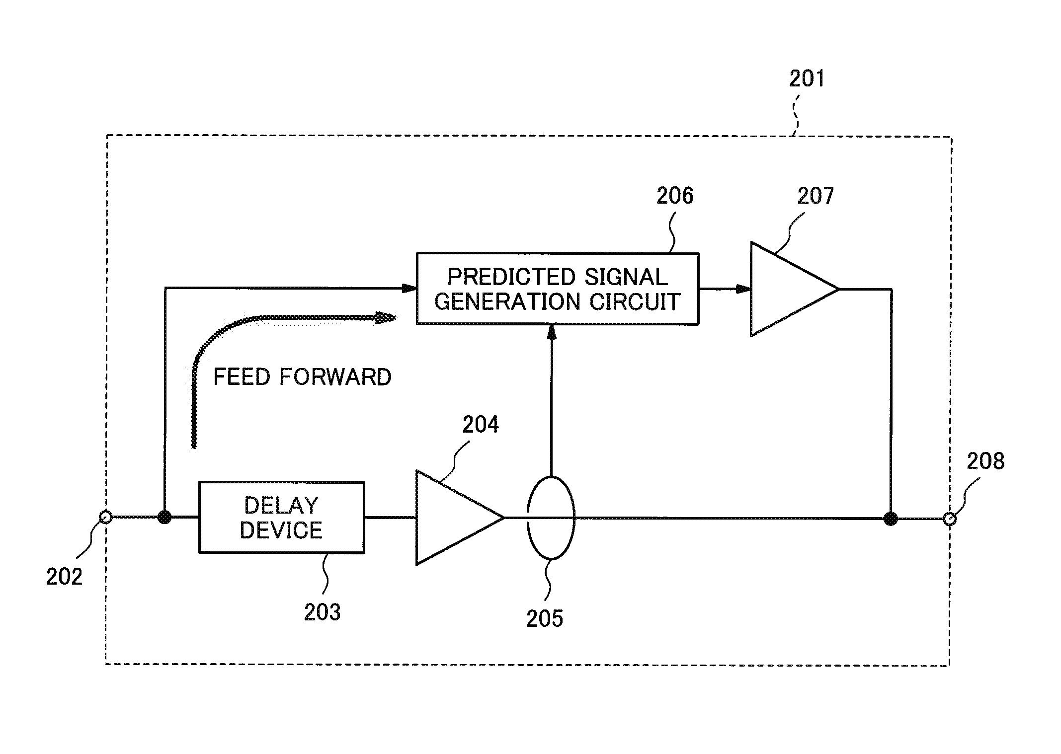
[0033]FIG. 1 is a block diagram showing an exemplary structure of a power supply circuit 201 according to the first exemplary embodiment of the present invention. The power supply circuit 201 includes: a signal input terminal 202, a delay device 203, a linear amplifier 204 (a first amplifier), a current detector 205, a predicted signal generation circuit 206, a switching amplifier 207 (a second amplifier) and a signal output terminal 208.

[0034]The signal input terminal 202 inputs a target signal of an amplification.

[0035]The delay device 203 makes the signal input from the signal input terminal 202 delayed for a set time and outputs the delayed signal.

[0036]The linear amplifier 204 amplifies the output signal of the delay device 203 and outputs the amplified signal to the signal output terminal 208.

[0037]The current detector 205 detects a current value of the signal which the linear amplifier 204 output to the signal output terminal 208 and outputs the ...

second exemplary embodiment

The Second Exemplary Embodiment

[0069]FIG. 5 is a block diagram showing an exemplary structure of a high frequency power amplifier 600 according to the second exemplary embodiment of the present invention. The high frequency power amplifier 600 includes: a high frequency modulation signal input terminal 601, a high frequency power amplifier 602, a high frequency modulation signal output terminal 603 and the power supply circuit 201.

[0070]In the high frequency power amplifier 600, a high frequency modulation signal to which an amplitude modulation or a phase modulation is applied is input to the high frequency power amplifier 602 via the high frequency modulation signal input terminal 601. On the other hand, an amplitude modulation signal of the high frequency modulation signal input from the high frequency modulation signal input terminal 601 is input to the power supply circuit 201 via the signal input terminal 202.

[0071]The signal input from the signal input terminal 202 is amplifi...


PUM


Abstract

In a power supply circuit which uses a switching amplifier in combination with a linear amplifier, in order to be capable of correcting errors of operation of the switching amplifier and the linear amplifier, that is to say, in order to cause the switching amplifier and the linear amplifier to operate in coordination in a near-ideal state, the power supply circuit is provided with first amplification unit for delaying an input signal by a predetermined set time and amplifying the input signal, current detection unit for detecting a current value of an output signal of the first amplification unit, predicted signal generation unit for generating a pulse signal on a basis of an output signal of the current detection unit and the input signal, second amplification unit for amplifying the pulse signal and signal output unit for combining current of the output signal of the first amplification unit and current of the output signal of the second amplification unit to output the combined current, wherein the set time is time for reducing an effect of delay times generated at the current detection unit, the predicted signal generation unit and the second amplification unit.

Description

TECHNICAL FIELD[0001]The present invention relates to a power supply circuit and a power supply control method.BACKGROUND ART[0002]Modulation methods adopted by wireless communications such as cellular phones of recent years have high frequency utilization efficiency and at the same time, high peak to average power ratio (PAPR: Peak to Average Power Ratio). In order to amplify a signal to which an amplitude modulation is applied using a class AB amplifier used in the field of wireless communications before now, it is necessary to secure enough back-off to maintain linearity. Generally, this back-off needs to be as much as PAPR at least. In contrast, efficiency of class AB amplifiers becomes highest at the time of power saturation, and declines as back-off becomes larger. For this reason, the larger the PAPR of a high frequency modulation signal becomes, the more difficult to raise power efficiency of a power amplifier will be.[0003]As a power amplifier which amplifies such a modulat...

Claims


Application Information

Patent Timeline
IPC IPC(8): H03F3/68
CPCH03F1/0222H03F1/0244H03F3/2173H03F3/68H03F2200/351H03F2200/432H03F2200/462H03F3/245
Inventor TAKAHASHI, KIYOHIKO
Owner NEC CORP
Why Eureka
Try Eureka