Error-correction method and error-correction device for an acceleration sensor

Active Publication Date: 2010-01-21
ROBERT BOSCH GMBH
View PDF12 Cites 4 Cited by
  • Summary
  • Abstract
  • Description
  • Claims
  • Application Information

AI Technical Summary

Benefits of technology

[0009]In one refinement of the exemplary embodiment, the method includes the following further steps: Applying an additional voltage to a third electrode for a third temperature in order to deflect the seismic mass; measuring a third current, which is caused by the deflection of the seismic mass, at a fourth electrode; applying the one additional voltage to the third electrode for a fourth temperature in order to deflect the seismic mass; measuring a fourth current caused by the deflection of the seismic mass, at the fourth electrode; and determining an additional correction variable on the basis of the third current and the fourth current. The first temperature may be identical to the third temperature; and the second temperature may be identical to the fourth temperature, or vice versa. Such a method makes it possible to correct systematic errors for an acceleration sensor that is able to measure accelerations in two different directions.
[0010]In

Problems solved by technology

Systematic errors of acceleration sensors having a plurality of electrodes (at least two) and a seismic mass are caused by deviations in the manufacture, among other reasons.
Especially for miniaturized accelerat

Method used


Image

  • Error-correction method and error-correction device for an acceleration sensor
  • Error-correction method and error-correction device for an acceleration sensor
  • Error-correction method and error-correction device for an acceleration sensor

Examples


Example

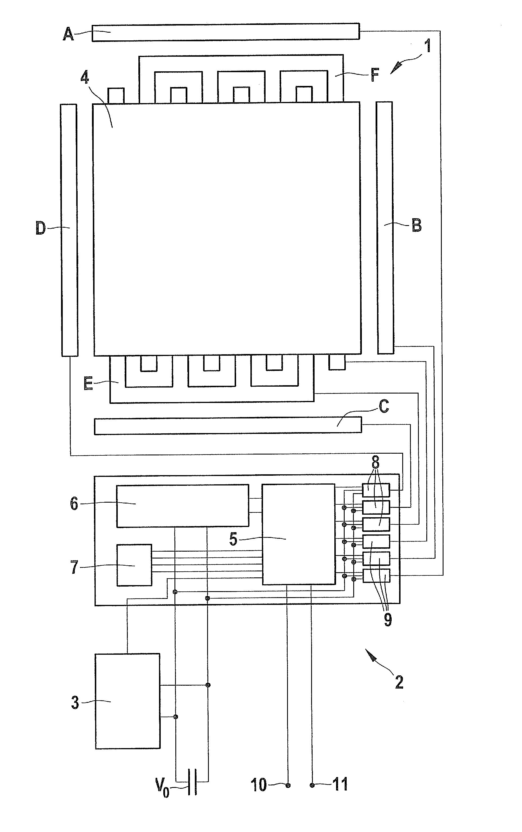
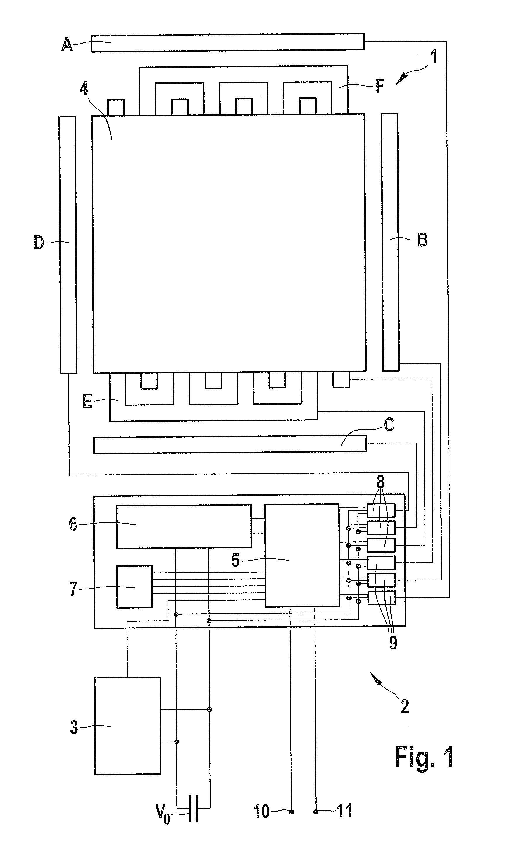
[0021]FIG. 1 shows a schematic view of an acceleration-measuring device. The acceleration-measuring device includes an acceleration sensor 1, an error-correction device 2, a temperature-measuring device 3, an input connection 10, and an output connection 11. Acceleration sensor 1, error-correction device 2 and temperature-measuring device 3 are integrated on one chip. Acceleration sensor 1 includes a plurality of electrodes A, B, C, D, E and F and a seismic mass 4. The seismic mass is suspended on springs in such a way that it is able to be moved in all directions. The electrodes form electrode pairs A and C, B and D, F and E. Via current supply lines an additional voltage is applied to electrodes C, D and E in each case. A current flowing through an associated current supply line is able to be measured at electrodes A, B and F.

[0022]Additional current supply lines of acceleration sensor 1 are not shown for reasons of clarity. Electrodes A, B, C and D are situated to the side of sei...


PUM


Abstract

An error-correction method for an acceleration sensor having a plurality of electrodes and a seismic mass. The error-correction method which makes it possible to correct systematic errors at low expense includes the following steps: applying a voltage in order to deflect the seismic mass; measuring a first current caused by the deflection of the seismic mass; measuring a second current caused by the deflection of the seismic mass; and determining a correction variable on the basis of the first current and the second current.

Description

RELATED APPLICATION INFORMATION[0001]The present application claims priority to and the benefit of German patent application no. 10 2008 040 529.9, which was filed in Germany on Jul. 18, 2008, the disclosure of which is incorporated herein by reference.FIELD OF THE INVENTION[0002]The present invention relates to an error-correction method and an error-correction device for an acceleration sensor, and to an acceleration measuring device having such an error-correction device.BACKGROUND INFORMATION[0003]Systematic errors of acceleration sensors having a plurality of electrodes (at least two) and a seismic mass are caused by deviations in the manufacture, among other reasons. Especially for miniaturized acceleration sensors produced by MEMS technologies such deviations are large. In order to eliminate such systematic errors and to detect a dependency from certain parameters, their measuring results can be compared to more precise measuring results from other acceleration sensors under ...

Claims


Application Information

Patent Timeline
IPC IPC(8): G01P21/00
CPCG01P21/00G01P15/125
Inventor BEER, LEOPOLD
Owner ROBERT BOSCH GMBH
Why Eureka
Try Eureka