System and method for correcting scan position errors in an imaging system

Inactive Publication Date: 2006-10-19
ECRM
View PDF5 Cites 5 Cited by
  • Summary
  • Abstract
  • Description
  • Claims
  • Application Information

AI Technical Summary

Benefits of technology

[0017] In yet another embodiment of the present invention, a system for correcting scan position error in an imaging system includes firmware for computing a nominal frequency tuning word used to control a rate of accumulation in a phase accumulator of a direct digital synthesizer (DDS) unit, determining a number of corrections per scan line of an image, determining a n

Problems solved by technology

It should be understood that position errors can also occur, for example, in drum type imaging systems, where such position

Method used


Image

  • System and method for correcting scan position errors in an imaging system
  • System and method for correcting scan position errors in an imaging system
  • System and method for correcting scan position errors in an imaging system

Examples


Example

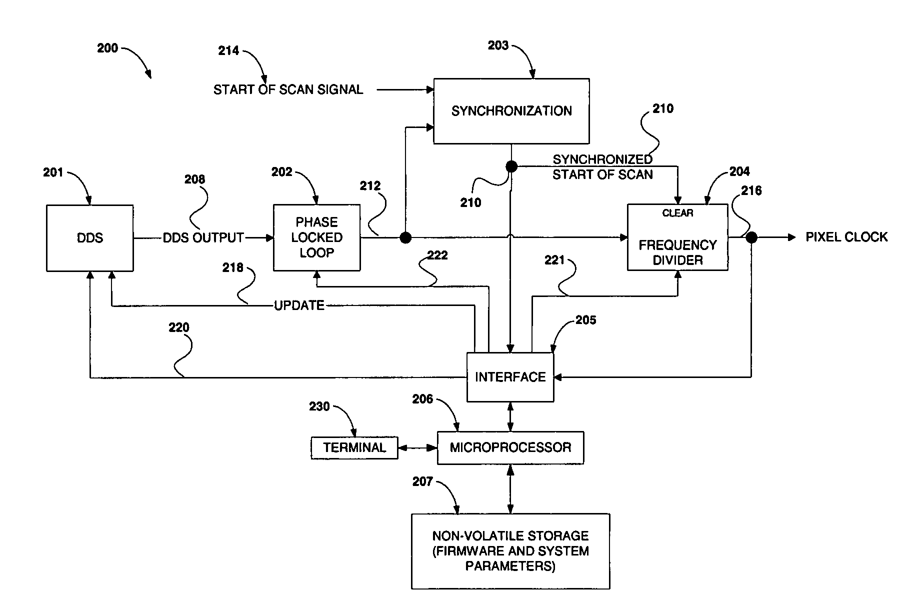
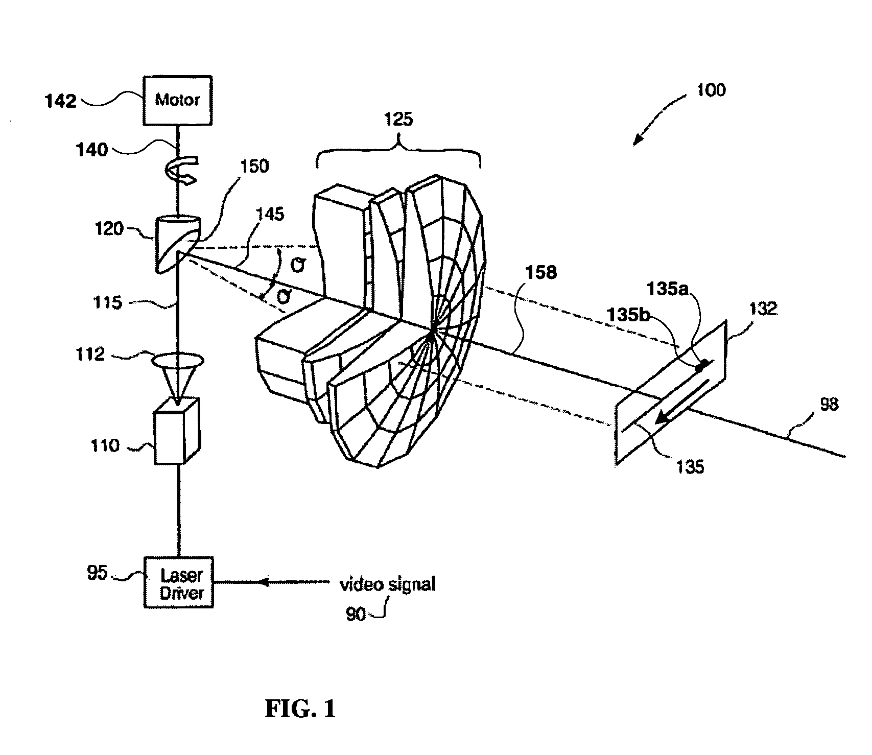
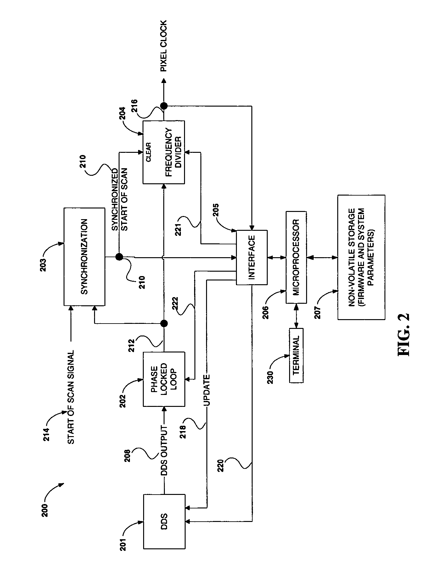
[0029]FIG. 2, generally at 200, is a block diagram of an exemplary system for correcting scan position errors in accordance with an embodiment of the present invention. FIG. 2 can thus be used, for example, in conjunction with system 100 shown in FIG. 1 to correct scan position errors. In particular, video signal 90 (FIG. 1) can be generated as a function of pixel clock frequency 216 (FIG. 2). As used herein, position error can be defined as the difference between the intended pixel position 135a and the actual pixel position 135b. Position error can be treated as a signed value, since the sign (positive or negative) can be used to indicate the direction of the error, and therefore the polarity of the required correction.

[0030] System 200 control is generally implemented and maintained by microprocessor unit 206 which, in one or more embodiments of the present invention, executes firmware stored in, for example, non-volatile storage 207. Microprocessor unit 206 can execute the firm...


PUM


Abstract

Embodiments of the invention provide systems and methods for correcting scan position errors in an imaging system. In one embodiment of the present invention, the method includes determining an image beam velocity error as a function of a position within a scan line of an image, and using the image beam velocity error to determine a plurality of pixel clock frequencies to be respectively applied to a plurality of positions within the scan line.

Description

BACKGROUND OF THE INVENTION [0001] 1. Field of the Invention [0002] The present invention generally relates to systems and methods for correcting scan position errors in an imaging system. [0003] 2. Background Description [0004]FIG. 1, generally at 100, is an illustration of a known flat field scanning system in which images can be plotted on a suitable medium, such as photosensitive material 132, from an electrical signal, such as an externally applied video signal 90 of the image. Video signal 90 modulates a power source such as laser driver 95, which, in turn, drives light source 110. Light source 110 converts video signal 90 into an image modulated visible or infrared light output that is collimated by lens 112 to form an image modulated light beam 115. Image modulated light beam 115 may be visible, infrared, or ultraviolet light and is generated by a laser, such as a helium neon laser or a semiconductor laser diode. Image modulated light beam 115 is deflected by a rotatable mir...

Claims


Application Information

Patent Timeline
IPC IPC(8): B41J2/435
CPCB41J2/471H04N1/047H04N1/1004H04N1/113
Inventor NILAND, M. JOSEPHCONNOR, DAVID J.TROXEL, DONALD E.CONNOLLY, JOHN L. III
Owner ECRM
Why Eureka
Try Eureka