
Scaffold Support Bracket and Assembly

a technology of support brackets and supports, which is applied in the direction of scaffold connections, building scaffolds, building aids, etc., can solve the problems of inability to allow the brace, lack of flexibility in the connection of two members together, etc., and achieves the effects of low cost, low manufacturing cost and simple design

Inactive Publication Date: 2007-08-16
SIMOES PORFIRIO
View PDF68 Cites 17 Cited by
  • Summary
  • Abstract
  • Description
  • Claims
  • Application Information

AI Technical Summary

Benefits of technology

[0013] In other words, cross members may be connected at any location along a vertical support tube. This design feature provides greater flexibility and minimizes the work involved in assembling the scaffold structure since the connection between vertical support tubes and cross members are not made at fixed locations or positions along the vertical support tubes. Another advantage is the reduction in moving parts on the bracket itself and material cost to manufacture it. Still another advantage is the use of fewer clamping connections so that the scaffold assembly can be built in less time.
[0018] It is an object of the present invention to provide a scaffold support bracket that is simple in design, has few moving parts and is economical to manufacture.
[0019] It is another object of the present invention to provide a scaffold support bracket that is readily adaptable to different scaffold applications and that is easily assembled and removed from a scaffold assembly.

Problems solved by technology

This does not offer flexibility in connection of two members together, as the brace does not allow for pivoting action.
Stated another way, the prior art does not allow the brace to be placed at any position along the vertical member.

Method used


Image

  • Scaffold Support Bracket and Assembly
  • Scaffold Support Bracket and Assembly
  • Scaffold Support Bracket and Assembly

Examples


Embodiment Construction

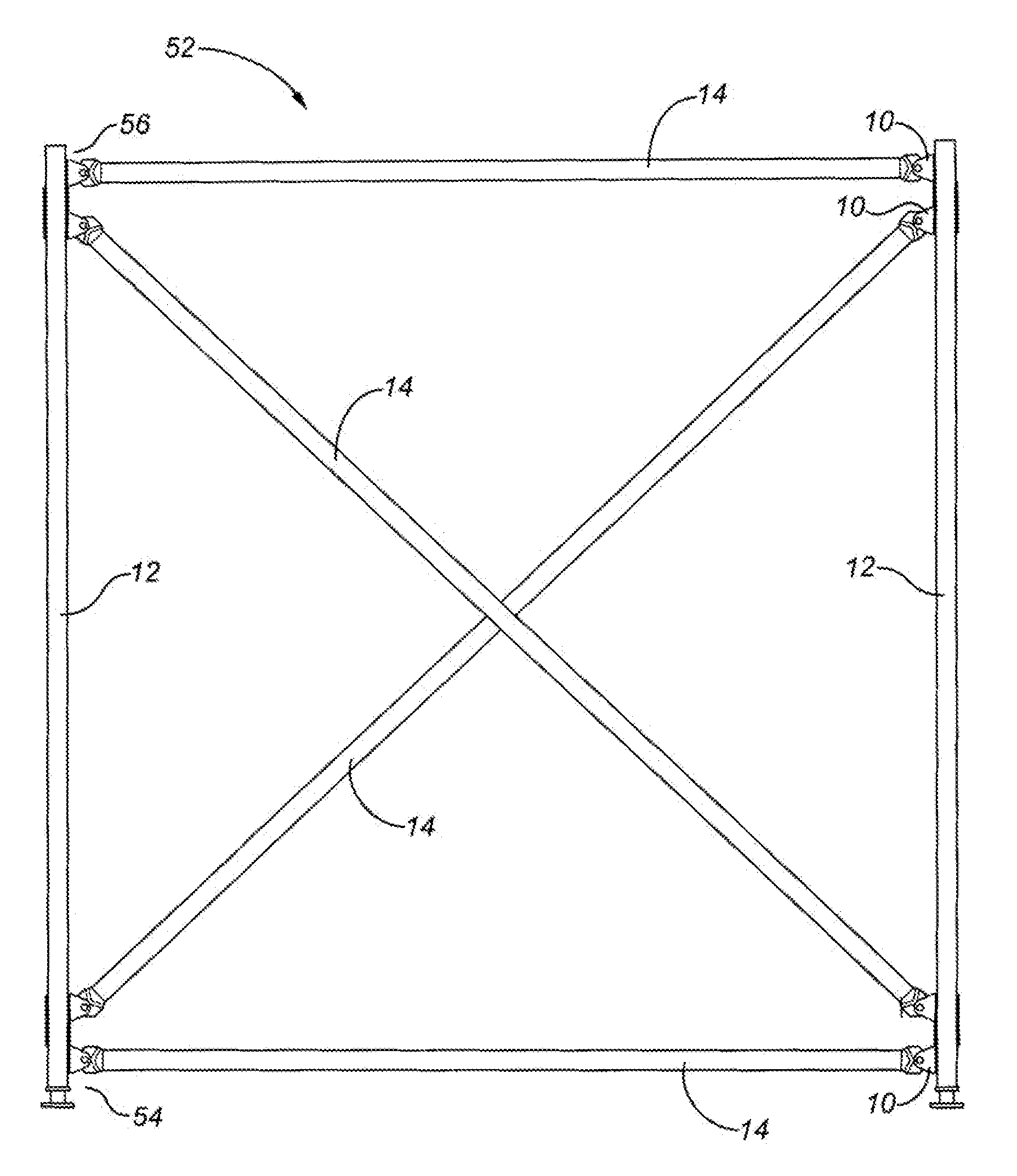
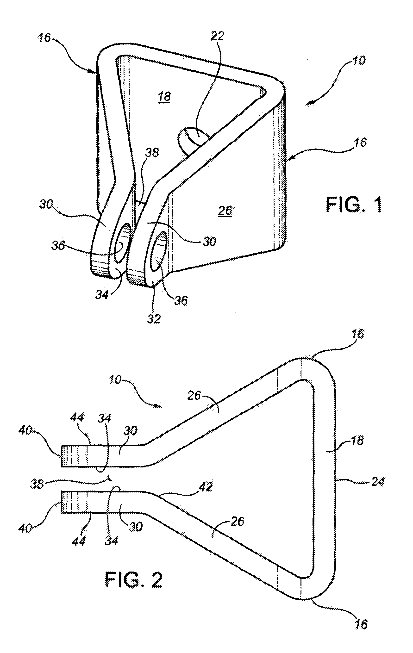
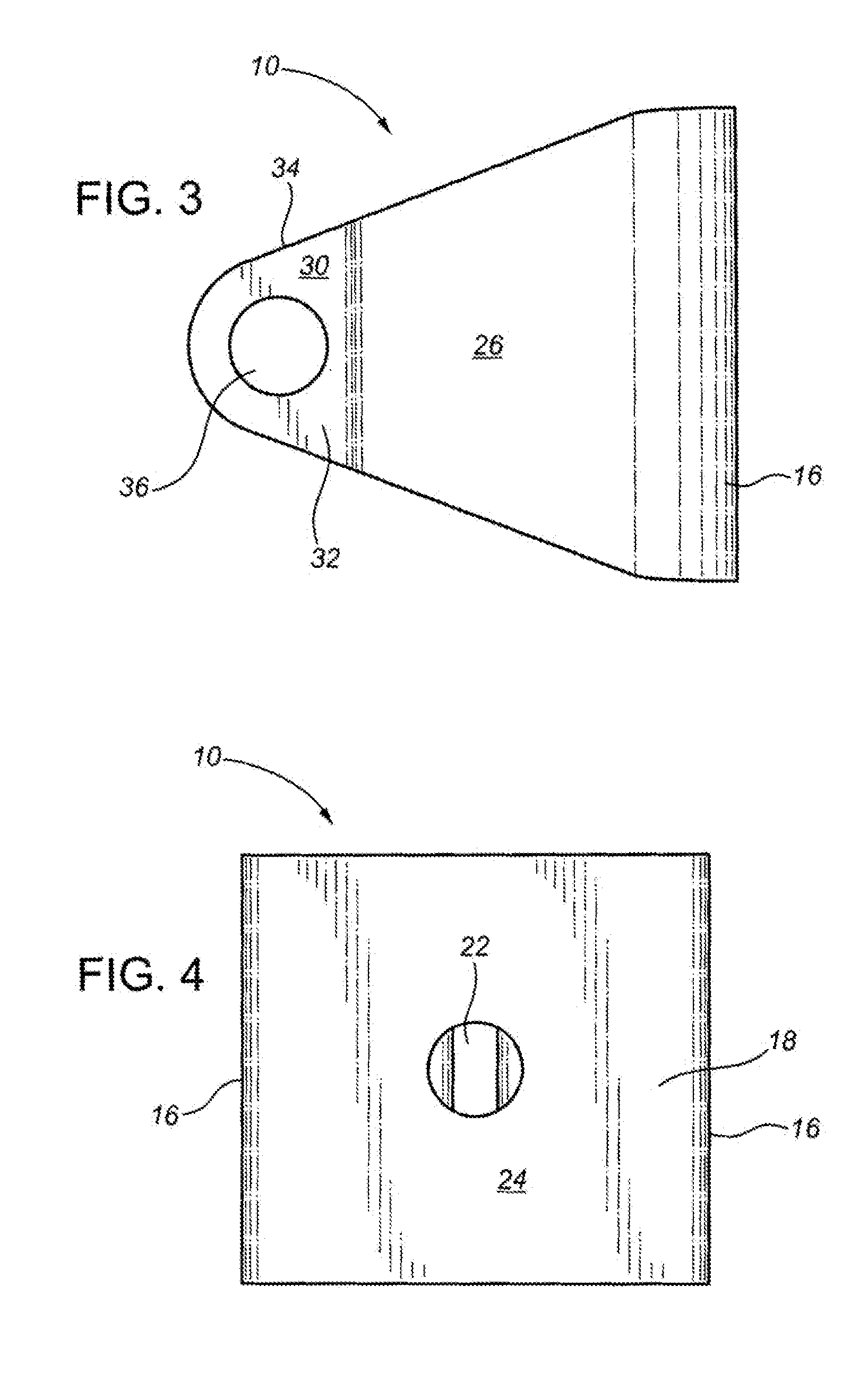
[0038] Referring to FIGS. 1 to 4, scaffold support bracket 10 is shown connecting a cross member to a vertical support tube to form a scaffold assembly. Bracket 10 comprises base member 18 at rear portion 20. Base member 18 comprises opposing sides 16 and is substantially vertical and planar and can be generally rectangular in structure. Aperture 22 is formed on base member 18 and extends therethrough. Aperture 22 is configured to receive a first fastener (not shown) therein for attachment to vertical support tube 12. Base member 18 has rear surface 24 that contacts and mates to the exterior surface of a vertical support tube as described in further detail below.

[0039] Base member 18 comprises a pair of arms 26 that extend generally forward from opposing sides 16 to define a horizontal axis of bracket 10. In the embodiment shown in FIG. 1, arms 26 are integrally joined to base member 18 although arms 26 may be attached to base member 18 by welding, for example. Arms 26 may be confi...


PUM


Abstract

A scaffold bracket has a vertical planar base member defining an aperture adapted to receive a fastener for connecting to a vertical support member. The base member has two arms extending forwardly from opposing sides of the base member to form a mouth or a slit sufficiently wide to accept a brace end of a cross member. Mutually aligned openings on the two arms are configured to receive a fastener for releasable connection to the brace end and allowing the cross member to pivot on the arm. Slots are provided on the arms and work in combination with a pin extending through the slots and the brace end to limit the pivotal movement of the cross member with respect to the bracket. A clamshell half clamp fastened to the base member allows the bracket to be releasably attached to a vertical support tube of a scaffold assembly at any location to provide increased flexibility in assembling the scaffold assembly.

Description

CROSS-REFERENCE TO FOREIGN PRIORITY APPLICATION [0001] This application claims priority from Canadian Application No. 2,535,970 entitled “Scaffold Support Bracket and Assembly,” which was filed by Porfirio Simoes on Feb. 10, 2006. [0002] 1. Field of the Invention [0003] The present invention relates to the field of scaffold assemblies and supportive devices therefor. More particularly, the present invention relates to a pivotable scaffold support bracket for releasably connecting a cross member to a vertical support tube. [0004] 2. Background of the Invention [0005] A scaffold assembly is a structure utilized during the construction phase of a building or when major services are required thereof. The scaffold assembly is assembled on site to provide a safe work platform for workers to have access to the building and is disassembled after use. [0006] The scaffold assembly consists of a plurality of vertical members and cross members, which are connected together using scaffold suppor...

Claims


Application Information

Patent Timeline
Patent Type & Authority Applications(United States)
IPC IPC(8): E04G1/00
CPCE04G7/307E04G7/22
Inventor SIMOES, PORFIRIO
Owner SIMOES PORFIRIO
Learn More