Diesel engine and supercharger

a diesel engine and supercharger technology, applied in the direction of electric control, piston pumps, instruments, etc., can solve the problem of no air flow control to regulate air, and achieve the effect of reducing parasitic losses, facilitating cold starting of diesel engines, and substantially constant diesel engine speed

Inactive Publication Date: 2010-06-01
HANSEN ENGINE
View PDF28 Cites 21 Cited by
  • Summary
  • Abstract
  • Description
  • Claims
  • Application Information

AI Technical Summary

Benefits of technology

[0011]The invention constitutes a four stroke diesel engine operably connected to a load, such as an electric generator, combined with a variable internal compression ratio supercharger for supplying varying amounts of air to the diesel engine to match the rate of air flow delivered to the diesel engine with the rate of air flow drawn by the diesel engine such that no air pressure rise occurs in the air intake manifold of the diesel engine when additional power output of the diesel engine is not required. The supercharger is a positive air displacement mechanism powered by the diesel engine. The supercharger has intake air flow controls that regulate the volume of air discharged by the supercharger to the diesel engine to maintain the speed of the diesel engine substantially constant when driving large variable loads than a smaller engine could without the supercharger. Air is moved through the supercharger with a pair of rotating screw rotors or one female and one male screw having cooperating helical grooves and protrusions or lands that create positive air flow to the diesel engine. The volume of air flow discharged by the supercharger is regulated by controlling the effective air pumping length of the screw rotors. A plurality of gates associated with the rotors control the air pumping operation of the rotors. Actuators, such as solenoids, connected to the gates function to move the gates between out and in positions relative to the rotors. When all of the gates are in the “in” positions a maximum volume of air is pumped by the supercharger into the diesel engine to facilitate cold starting of the diesel engine. The volume of the air supplied to the diesel engine by the supercharger is changed by selectively moving the gates between their out and in positions. A controller responsive to the speed and load on the engine actuates the solenoids to control the volume of air supplied to the diesel engine to maintain the diesel speed and load requirements of the diesel engine. The variable compression ratio supercharger produces the lowest parasitic losses to the system by minimizing the pumping work required of the supercharger to meet the current load requirement.

Problems solved by technology

There are no air flow controls to regulate air flowing into and out of the supercharger.

Method used


Image

  • Diesel engine and supercharger
  • Diesel engine and supercharger
  • Diesel engine and supercharger

Examples


Embodiment Construction

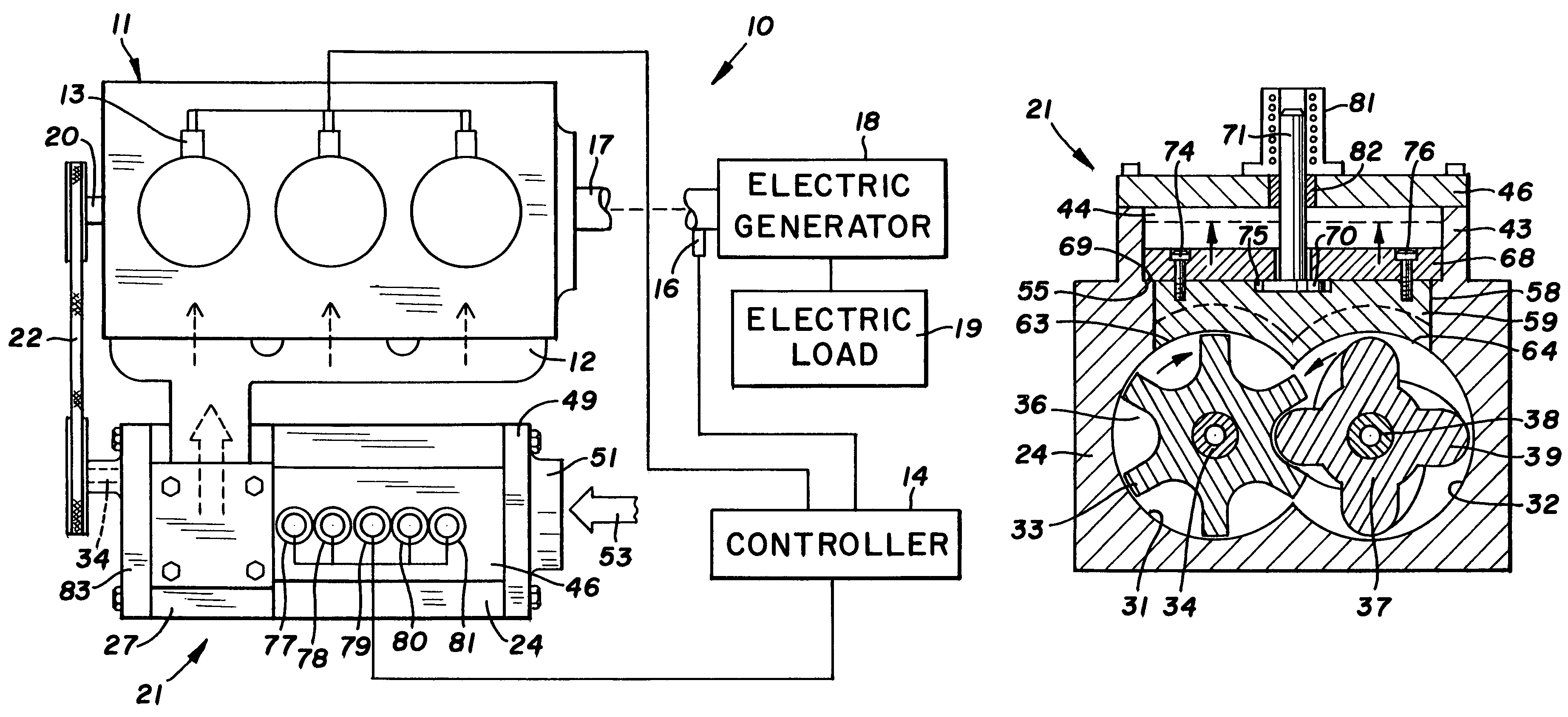
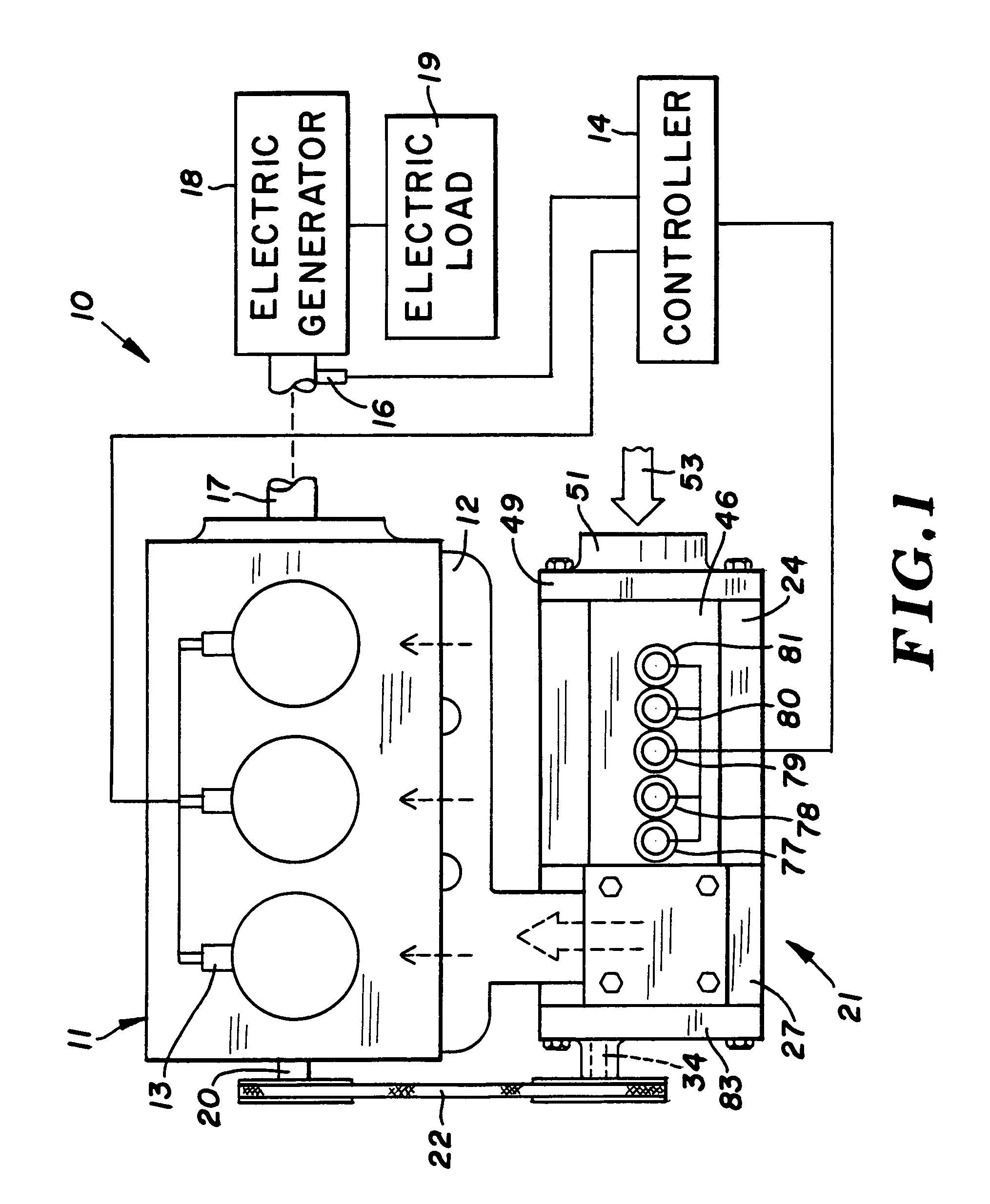
[0028]The supercharged diesel engine system 10 of the invention, shown in FIG. 1, has a conventional four stroke internal combustion piston engine 11 that uses the heat of highly compressed air to ignite a spray of fuel, such as hydrocarbon fuel oil introduced into the combustion chambers. This type of internal combustion engine is known as a four stroke diesel engine. Engine 11 includes an air intake manifold 12 for accommodating an air supply for the combustion chambers of the engine. Fuel injectors 13 have solenoids wired to a controller 14 operable to timely supply hydrocarbon fuel, known as diesel fuel, to the combustion chambers of engine 11. Controller 14 is wired to a sensor 16 that senses the timing and rotational speed of the output or drive shaft 17 of engine 11. The signals from sensor 16 are processed by the electronic components of controller 14 whereby controller 14 generates electric output energy that timely actuates injectors 13 to discharge fuel into the combustio...


PUM


Abstract

A four stroke diesel engine combined with a supercharger is operable to supply varying amounts of air to the engine responsive to the load on the engine. The supercharger has a pair of rotors driven by the engine operable to move air to the engine. Gates associated with the rotors control the amount of air and pressure of the air moved by the rotors to the diesel engine.

Description

CROSS REFERENCE TO RELATED APPLICATION[0001]This application claims the benefit of the priority of U.S. patent application Ser. No. 60 / 666,891 filed Apr. 1, 2005.FIELD OF THE INVENTION[0002]The technology of the invention relates to internal combustion diesel engines equipped with superchargers for supplying air to the engine according to the speed and load of the engines to increase the performance of the engines.BACKGROUND OF THE INVENTION[0003]Air displacement devices have been developed and used to increase the supply of air and fuel to internal combustion engines to boot engine horsepower. An example of an air displacement device is the “Roots blower” shown by P. H. Roots in U.S. Pat. No. 30,157 and G. Scheerer in U.S. Pat. No. 2,201,014. This device has a belt-driven shaft that drives two close-clearance rotors. The rotating rotors during each rotation sweep out a specific volume of air to an air receiver, such as an internal combustion engine. The rotational speed of the roto...

Claims


Application Information

Patent Timeline
Patent Type & Authority Patents(United States)
IPC IPC(8): F02B33/00F01C1/16G06F19/00G06F7/00G06F17/00F02B33/44F04B49/00F04C18/00F04C2/00F04B17/00F01C1/24
CPCF02B33/38F02D29/06F02D41/0007F04C18/16F04C23/006F04C28/18F02D41/021F02B39/04Y02T10/144F02D41/064Y02T10/12
Inventor HANSEN, CRAIG N.CROSS, PAUL C.
Owner HANSEN ENGINE
Why Eureka
Try Eureka