Surgical dental appliance

a dental appliance and surgical technology, applied in the field of surgical dental appliances, can solve the problems of reducing affecting the accuracy of dental appliance positioning, and requiring surgery, so as to reduce the uncertainty of relative positions, quick remove the appliance, and facilitate the re-establishment of bite relationship

Active Publication Date: 2008-04-08
ALIGN TECH
View PDF56 Cites 136 Cited by
  • Summary
  • Abstract
  • Description
  • Claims
  • Application Information

AI Technical Summary

Benefits of technology

[0006]Advantages of the invention may include one or more of the following. The system provides a dental appliance for the temporary passive splinting of teeth. The system fixes the relative positions of the two arches and allows for mounting or positioning the inter arch-relationship during surgery using the appliances. The system allows the doctor to plan the desired treatment on a computer.
[0008]The surgeon can send the dental records and impressions of the patient to an appliance fabricator. The fabricator can digitally set bite relationship and fabricate appliances with index points which allow the surgeon to easily re-establish bite relationship during surgery with the appliances inserted into the patient's teeth.
[0009]The setting of the occlusion is benefited by the incorporation into the splint of a means of indexing several opposing points on the arches. These points are guides to mitigate or eliminate uncertainty in the relative positions. The design of the appliance index points may be in any configurations that will allow easy bite setting and bite recreation for the surgeon. The appliance material may have physical properties for precise fitting over the teeth of the patient and should also be easily removable due to the post surgical fragile state of the patient. The appliance material may have environmental switching properties for changing physical properties for easy removal and insertion purposes. The appliance material may have the ability to carry active ingredients and release it in a controlled fashion. The active ingredients may be fluoride and / or any therapeutic compounds. The appliance material may be transparent or having tooth matching color.

Problems solved by technology

Surgery may be required because the bite relationship is so severe that it is beyond the ability of conventional orthodontia.
This method also can only be applied by the dentist who is familiar with it; moreover, the rigidity of the holding elements renders their exact positioning more difficult.
This method could not be implemented, however as it is difficult to shape the synthetic material exactly and, on the other hand, it often does not withstand the forces which arise in the area of the teeth, and the removal of the synthetic material has also proved difficult.
This present method of fabricating the guide template and manually setting the bite using study models is time consuming, inaccurate and cumbersome.

Method used


Image

  • Surgical dental appliance
  • Surgical dental appliance
  • Surgical dental appliance

Examples


second embodiment

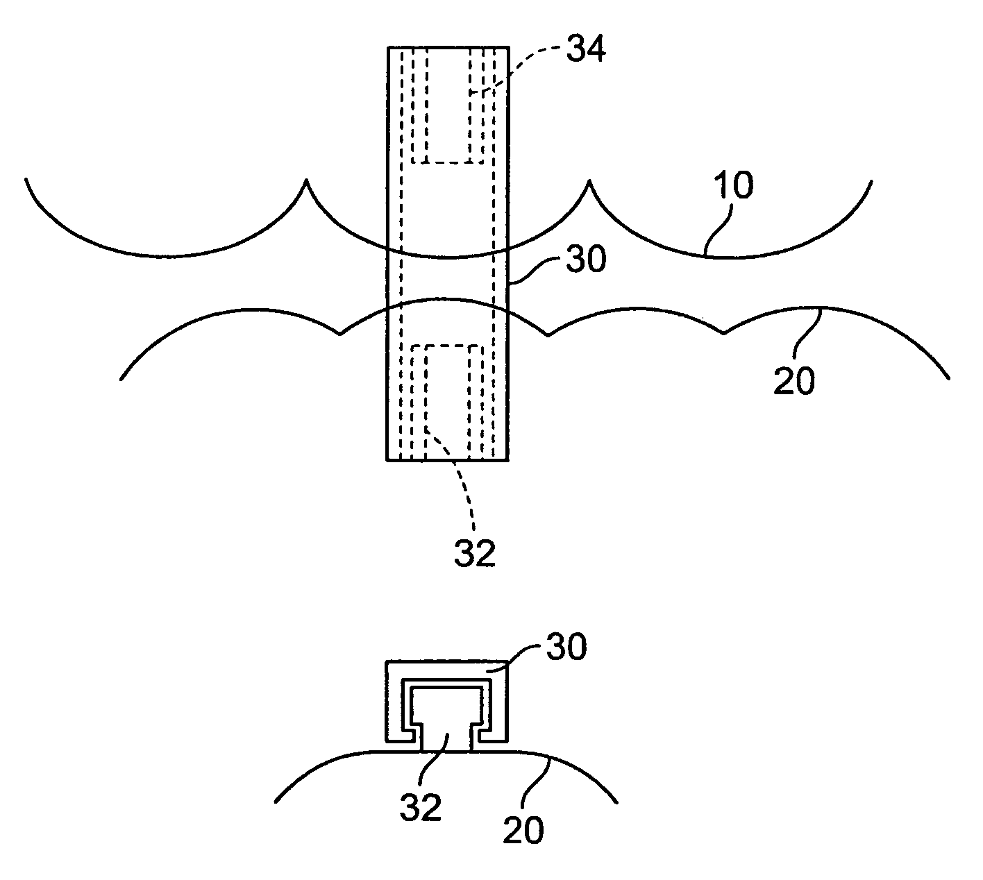
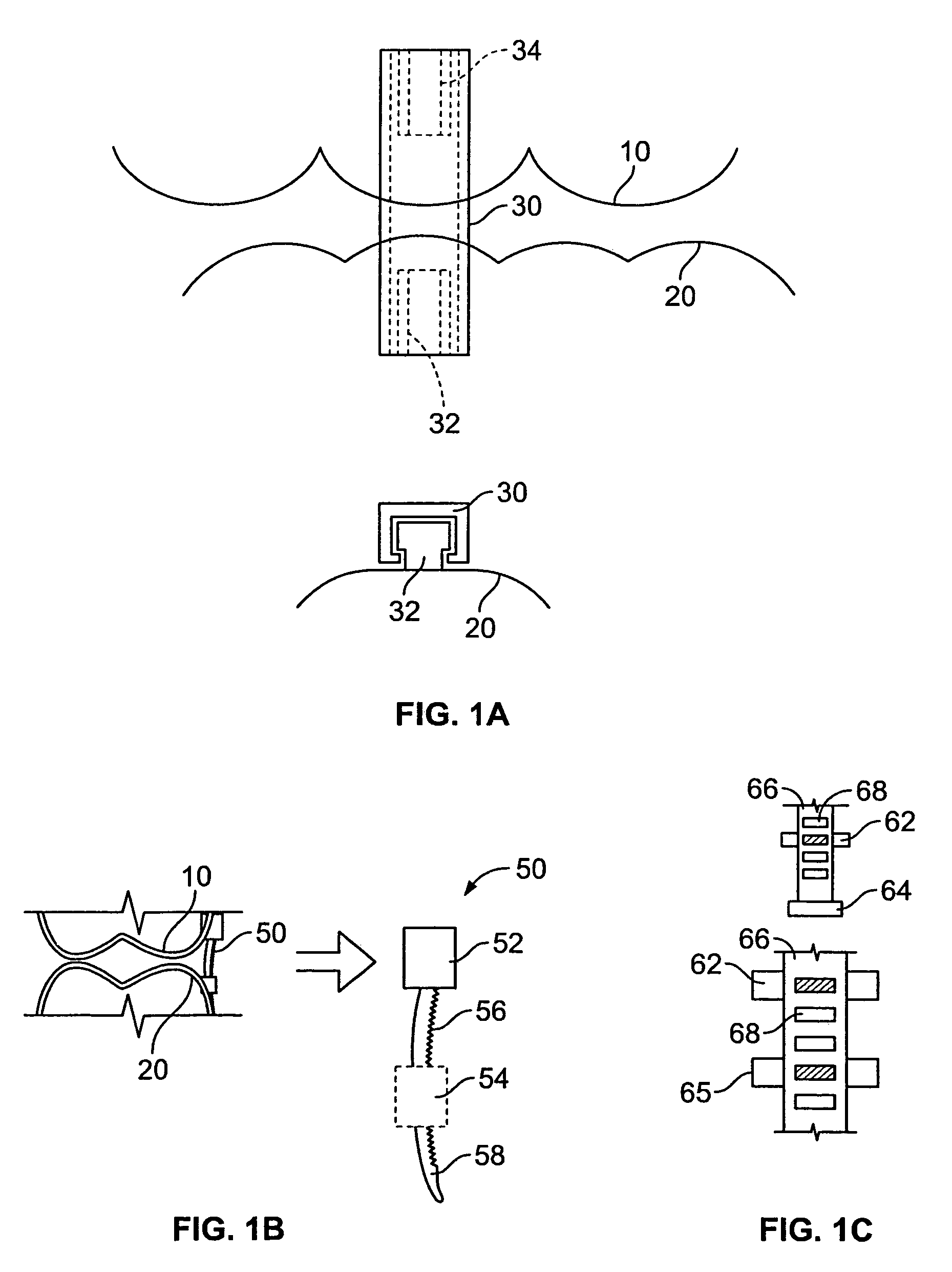
[0026]FIG. 1B shows a connection member 50. In this embodiment, the connection member 50 includes an upper portion 52 affixed to the upper appliance 10 and a ratcheted portion 56. The upper and ratcheted portion 52 and 56 are one piece in one embodiment. A lower portion 54 is affixed to the lower appliance 20 and is a separate element. A section of 50 projects beyond the portion 54, and pulling on this section 58 brings the upper and lower appliances 10 and 20 (and by extension, upper and lower jaws) closer together and more firmly or solidly fixes their positions relative to each other.

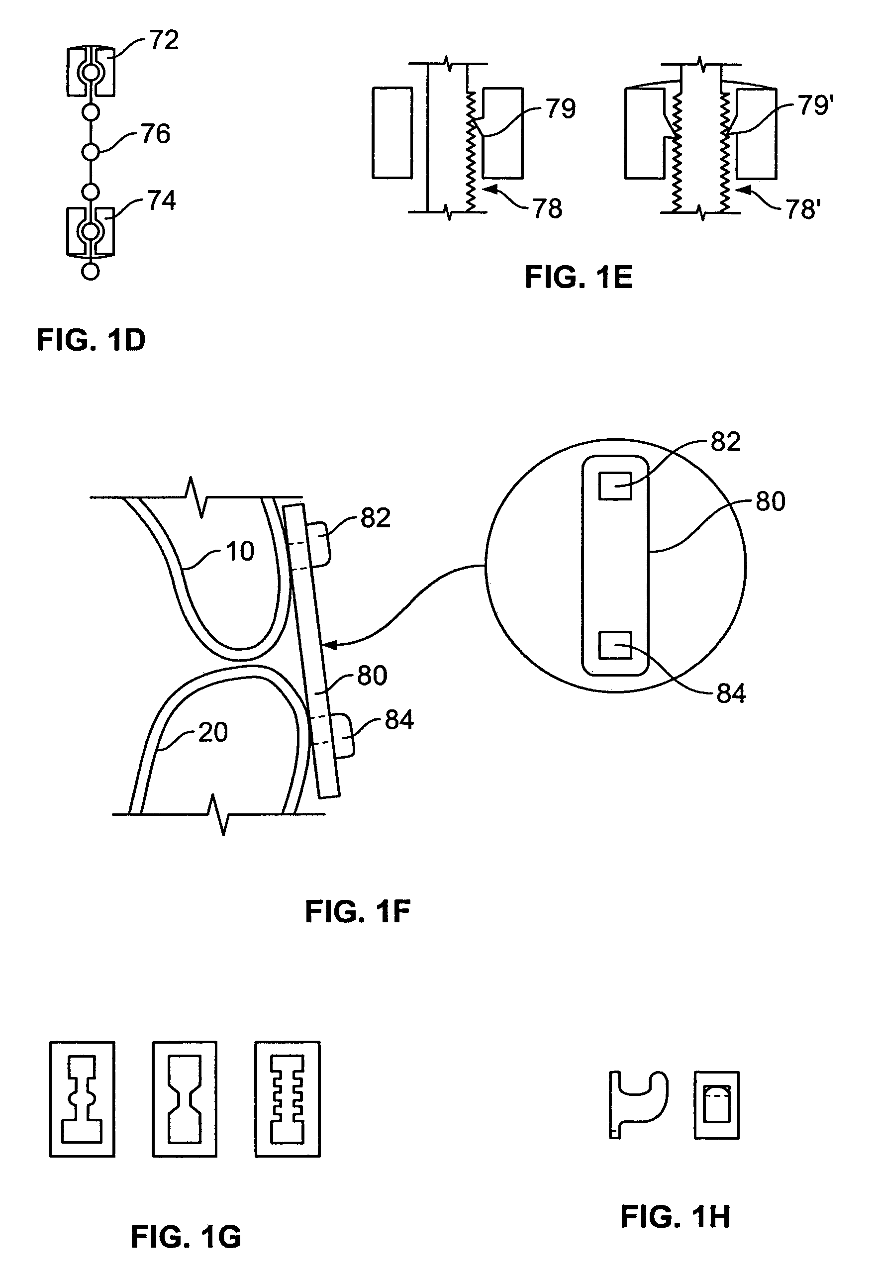
[0027]Other similar embodiments include but are not limited to a ladder connection member (FIG. 1C), a bead connection member (FIG. 1D), and a pawl / ratchet connection member (FIG. 1E).

[0028]In FIG. 1C, an upper portion 62 is a separate element. The upper portion 62 has a base which is mounted on one of the appliances 10 or 20 and an extended portion which projects from the appliance. A ladder 66 has ...

third embodiment

[0032]FIG. 1F shows a third embodiment where the inter-arch fixation component is a rectilinear hasp 80 that snaps onto or over hook elements 82 and 84 to prevent relative motion between the upper and lower arches. The hook line elements also have a mainly rectilinear profile in the buccolingual direction. Rather, they are for engaging elastics when the hasps are removed. The hook elements are bonded to or embedded in the aligners.

[0033]The approximately intimate contact between the parallel sides of the hasp holes and the hooks prevents lateral shifting of the aligners relative to each other because the hasp holes cannot rotate about the hook elements. When a sufficient number (for example three or more) of these assemblies are placed on the dental arch form, the upper and lower arches cannot shift.

[0034]All other possible motion will be prescribed as well. When desired, the hasps may be easily removed by cutting them in one or more places. Various design iterations such as those s...


PUM


Abstract

A dental splint includes upper and lower appliances having cavities shaped to receive teeth on a patient's maxillary and mandibular arches, respectively; and a connection member adapted to fixedly secure the upper and lower appliances together.

Description

BACKGROUND OF THE INVENTION[0001]Some people need surgery to correct maxilla to mandible relationship for better occlusion. Surgery may be required because the bite relationship is so severe that it is beyond the ability of conventional orthodontia. During such treatment, the bones are repositioned and splints are used in order to bring about temporary intramandibular, intramaxillary or intermaxillary fixations in jaw surgery. During surgery, one or both jaws are cut free from neighboring bone and tissue. The surgeon brings the dental arches into the desired occlusion and fixes the jaw(s) in the new relative position(s). Steps are then taken to secure the jaw(s) to the bone and tissue again. To help maintain the intended occlusion as healing occurs, the jaws are connected to each other using a splint.[0002]As discussed in U.S. Pat. No. 5,184,955 to Baer, et al., a dislocated and repositioned tooth is connected to its neighboring teeth by means of a metal wire which, after an etching...

Claims


Application Information

Patent Timeline
Patent Type & Authority Patents(United States)
IPC IPC(8): A61C5/00A61C3/00A61C7/08A61C7/36A61C19/06
CPCA61C7/08A61C7/36A61C19/063B33Y80/00
Inventor ABOLFATHI, AMIRPHAN, LOC X.KNOPP, PETER
Owner ALIGN TECH
Why Eureka
Try Eureka