Circuit board having at least one auxiliary scribed line

a technology of circuit boards and scribed lines, which is applied in the direction of printed circuit aspects, programmable/customizable/modifiable circuits, and connection devices, etc., can solve the problems of increasing the cost, occupying the internal space of the mainframe, and more working hours, so as to achieve the effect of reducing the manufacturing cost of the circuit board provided by the present invention, reducing the cost of manufacturing, and improving the quality

Inactive Publication Date: 2008-05-27
INVENTEC CORP
View PDF7 Cites 0 Cited by
  • Summary
  • Abstract
  • Description
  • Claims
  • Application Information

AI Technical Summary

Benefits of technology

[0013]In view of the above, because the circuit board provided by the present invention is manufactured through the same process and then cut so as to be applied in notebook computers with different sizes, compared with the conventional arts, the manufacturing cost of the circuit board provided by the present invention is lower and the manufacturing process is simpler. Since the circuit board provided by the present invention is cut to be disposed in the mainframes of the notebook computers with different sizes, compared with the conventional arts, the circuit board provided by the present invention is not required to be electrically connected to the medium circuit board. Accordingly, the circuit board provided by the present invention does not occupy more internal space of the mainframes, and the signal transmitted by the connectors of the circuit board provided by the present invention has a preferable quality.

Problems solved by technology

However, the manufacturing cost is high if the mainboards with different sizes are manufactured through different processes.
However, the medium circuit board 10 and the connection cable 120 causes an increase of the cost and occupies the internal space of the mainframes, and also more working hours must be spent in assembling the medium circuit board 10 and the connection cable 120.

Method used


Image

  • Circuit board having at least one auxiliary scribed line
  • Circuit board having at least one auxiliary scribed line
  • Circuit board having at least one auxiliary scribed line

Examples


Embodiment Construction

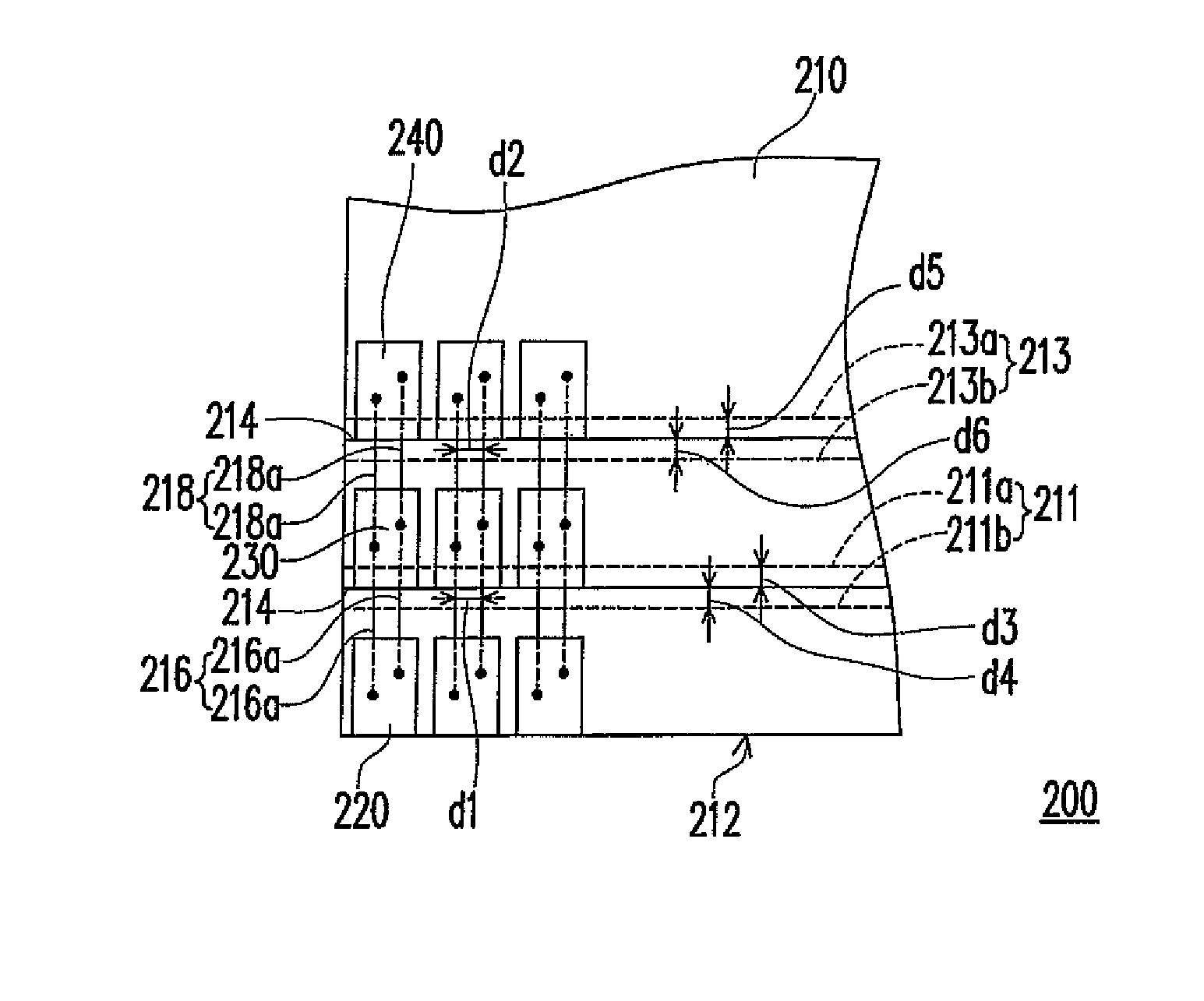
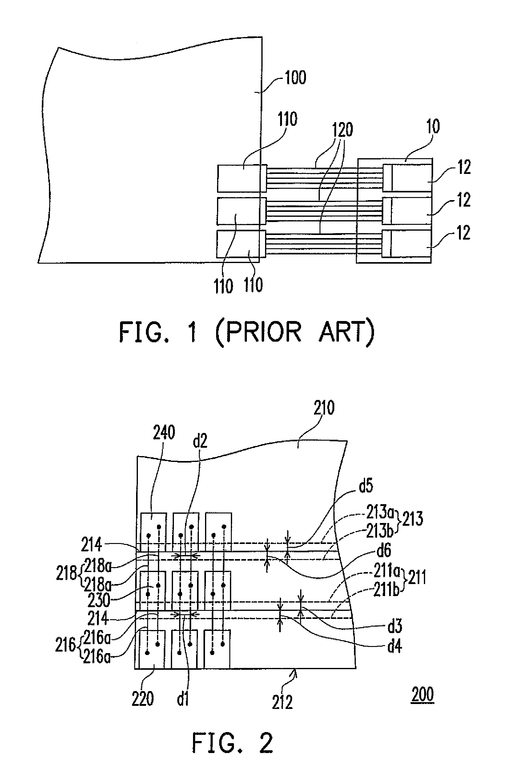
[0020]FIG. 2 is a schematic view of a circuit board according to an embodiment of the present invention. Referring to FIG. 2, the circuit board 200 of this embodiment is, for example, a mainboard, and includes a board body 210, at least one first connector 220 (three first connectors 220 schematically shown in FIG. 2), and at least one second connector 230 (three second connectors 230 schematically shown in FIG. 2). The board body 210 has an edge 212 and at least one auxiliary scribed line 214 (two auxiliary scribed lines 214 schematically shown in FIG. 2), and the auxiliary scribed lines 214 are substantially parallel to the edge 212. Furthermore, the circuit board 200 of this embodiment further comprises at least one third connector 240 (three third connectors 240 schematically shown in FIG. 2).

[0021]The first connectors 220 are disposed on the board body 210 and adjacent to the edge 212, the second connectors 230 are disposed on the board body 210 and adjacent to one of the auxil...


PUM


Abstract

A circuit board including a board body, at least one first connector, and at least one second connector is provided. The board body has an edge and at least one auxiliary scribed line. The auxiliary scribed line is substantially parallel to the edge. The first connector is disposed on the board body and adjacent to the edge. The second connector is disposed on the board body and adjacent to the auxiliary scribed line. The second connector is electrically connected to the first connector. The first connector and the second connector are located on the different sides of the auxiliary scribed line.

Description

CROSS-REFERENCE TO RELATED APPLICATION[0001]This application claims the priority benefit of Taiwan application serial no. 95144450, filed on Nov. 30, 2006. All disclosure of the Taiwan application is incorporated herein by reference.BACKGROUND OF THE INVENTION[0002]1. Field of the Invention[0003]The present invention relates to a circuit board. More particularly, the present invention relates to a circuit board having at least one auxiliary scribed line.[0004]2. Description of Related Art[0005]Generally speaking, a conventional circuit board for carrying and electrically connecting a plurality of electronic components is mainly constituted of a plurality of wiring layers and a plurality of insulating layers which are stacked alternately. The wiring layers are formed of copper foils via a lithography / etching process, and the insulating layers are disposed between the adjacent wiring layers respectively, so as to isolate the wiring layers. Furthermore, the stacked wiring layers are el...

Claims


Application Information

Patent Timeline
Patent Type & Authority Patents(United States)
IPC IPC(8): H01R27/00
CPCH05K1/0286H05K1/117H05K3/0052H05K2201/0909H05K2201/0979
Inventor LIN, TSAN-YUN
Owner INVENTEC CORP
Why Eureka
Try Eureka