Solid-liquid separator using roller system

a technology of solid-liquid separator and roller system, which is applied in the direction of filtration separation, sedimentation settling tank, separation process, etc., can solve the problems of large load on the screen, leakage of solid-liquid mixture from gaps other than the filtration surface, damage, etc., to achieve high sealability, constant water content of okara, and heighten the effect of fitting or plane accuracy

Inactive Publication Date: 2013-08-13
TAKAI TOFU & SOYMILK EQUIP
View PDF21 Cites 0 Cited by
  • Summary
  • Abstract
  • Description
  • Claims
  • Application Information

AI Technical Summary

Benefits of technology

[0015]When making the description on condition that the solid-liquid mixture is soybean soup for producing tofu, fried bean curd and the like, that the solid component is okara and that the liquid component is soymilk, since the pressure application lid keeps the pressure constant irrespective of the concentration or viscosity of the soybean soup or of the fluctuation of the residue, okara having the squeezing degree kept constant is discharged from the discharge window and, within the casing, soymilk having a homogenous concentration and a preferable quality (having a protein high-level structure and an emulsified state retained and containing a small amount of residue) is separated with the rollers. In addition, mere adjustment of the pressure to be exerted on the pressure application lid enables the degree of extraction of the solid component to be simply adjusted at a moment even during the operation. Furthermore, in the present invention, the passageway can fully be closed from one side between the paired rollers and the pressure application means is kept substantially constant and stable with the air pressure, thereby making the water content of okara constant. Since the retention portion has a constant volume, may have a passageway for it or a squeezing passageway wider gradually toward the discharge window, and is difficult to close, it can handle various properties of the solid substance.
[0023]According to the present invention, the solid-liquid mixture is supplied in a state of being appropriately pressurized by the supply means and, at the same time, the solid component is discharged from the gap between the pressure application lid and the discharge window disposed on the other side between the paired rollers out of the discharge window. With this configuration, it is possible to easily discharge the solid component containing a constant amount of water out of the discharge window, even when the amount of the solid-liquid mixture to be supplied is optionally changed, without taking notice of the rotation speed of the rollers, the ratio of the solid component in the solid-liquid mixture and the concentration of the liquid component as has heretofore been done. With this simple configuration, it is possible to discharge the solid component having a constant quality (water content) out of the discharge window and, at the same time, mere adjustment of the pressure to be exerted onto the pressure application lid by means of the pressure application means enables the degree of squeezing of the solid component to be simply adjusted at a moment even during the operation. In addition, with this simple structure, it is possible to treat a great deal of the solid-liquid mixture for a short period of time without inducing clogging. Furthermore, by using the pressure application lid and disposing packing between the pressure application lid and the discharge window, it is easy to bring the interior of the casing to a fully closed state and to perform automatic circulation cleaning. That is to say, it is possible to treat a great deal of the solid-liquid mixture for a short period of time and becomes easy to perform cleaning.

Problems solved by technology

In the case of a pump exhibiting unduly high discharge pressure, there is a possibility of the solid-liquid mixture being leaked from gaps other than the filtration surface or of the screen that is the filtration surface being loaded greatly and damaged.

Method used


Image

  • Solid-liquid separator using roller system
  • Solid-liquid separator using roller system
  • Solid-liquid separator using roller system

Examples


second embodiment

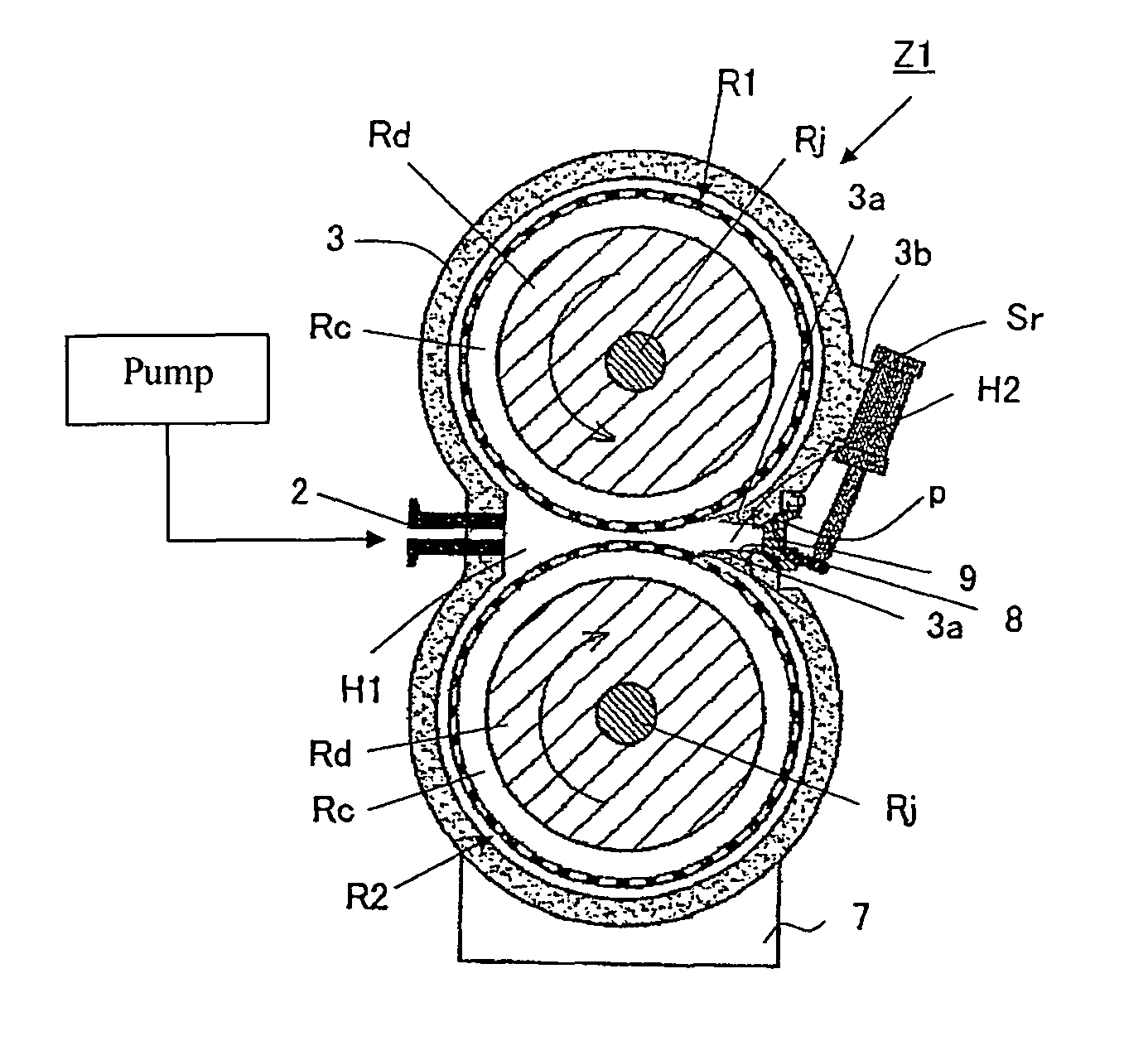
[0058]FIG. 6 is a cross section showing a solid-liquid separator Z3 having a roller system according to the present invention. In the present embodiment, paired scrapers 6 are attached as directed to the upper and lower rollers R1 and R2, respectively. That is to say, unlike the solid-liquid separator Z2 having the roller system, the passageway T1 and T2 are not provided here. The paired scrapers 6 are disposed to guide, without any modification, the solid-liquid mixture that has been supplied and passed between the upper and lower rollers R1 and R2 in the direction of the discharge window 8. That is to say, a region H2 on the discharge side is defined by the upper and lower rollers R1 and R2, the upper and lower scrapers 6 and a pressure application lid 9 on the wall of a casing 3 that is disposed close to the scrapers. It is possible for the upper and lower scrapers 6 to be attached as being spread in proportion as the scrapers are directed toward the discharge window 8. In this c...

first embodiment

[0059]In addition, a region H1 on the supply side is set to be larger than the region H2 on the discharge side. In comparison with the first embodiment, therefore, the solid-liquid mixture to be supplied from the region H1 on the supply side can readily pass through the region H2 on the discharge side to allow the solid component in a half-extracted state to readily pass in synchronization with the rotation of the rollers. For this reason, the extraction time can be shortened to enhance the apparatus performance, make the phenomenon of the solid substance rubbing the surface of the screens on the rollers (the so-called “grater” phenomenon) hard to occur and enable the liquid component (soymilk) containing a small amount of minute solid substances (residues in the soymilk, for example) to be obtained. In addition, when the cross-sectional area of the solid substance to be discharged becomes large, the solid substance always filling the region H2 on the discharge side causes the entir...


PUM

PropertyMeasurementUnit
pressureaaaaaaaaaa
pressureaaaaaaaaaa
discharge pressureaaaaaaaaaa

Abstract

A solid-liquid separator using a roller system includes a casing, rollers disposed within the casing and each provided with a screen that is formed in an outer periphery thereof with plural pores, a supply device disposed outside the rollers for supplying into the casing under appropriate pressure a solid-liquid mixture to be separated into a solid component via the plural pores and a liquid component filtered inside, a casing wall disposed adjacent to the rollers after the solid-liquid mixture supplied with the supply device is passed through the rollers rotated, a discharge window formed in the casing wall for discharging the solid component, and a pressure application lid formed on the casing wall for stably applying prescribed pressure in a direction of closing the discharge window with a pressure application device. The liquid component is separated from the solid-liquid mixture by means of the rollers and the solid component is discharged from the discharge window on which pressure has been exerted by means of the pressure application lid.

Description

RELATED APPLICATIONS[0001]The present application is based on, and claims priority from, Japanese Application No. JP2009-255859, filed Nov. 9, 2009, the disclosure of which is hereby incorporated by reference herein in its entiretyBACKGROUND OF THE INVENTION[0002]1. Field of the Invention[0003]The present invention relates to a solid-liquid separator using a roller system, equipped with rollers each having a screen formed in the outer periphery thereof with plural pores, for separating a solid-liquid mixture into a solid component and a liquid component via the plural pores.[0004]2. Description of the Prior Art[0005]There has heretofore been known a solid-liquid mixture separator for separating liquid through filtration from a solid-liquid mixture having a solid substance and a liquid substance mixed with each other, in which cited as the solid-liquid mixture is a solid-liquid mixture (so-called “boiled soybean-water slurry” that is hereinafter referred to also as “soybean soup” in ...

Claims


Application Information

Patent Timeline
Patent Type & Authority Patents(United States)
IPC IPC(8): B01D33/06B01D33/76B30B9/20A23L11/00
CPCB01D33/073B01D33/37B30B9/20B01D33/646B01D33/466B30B9/26C02F11/126A23L11/07A23L11/65A23L11/45
Inventor TAKAI, TOICHIROUEDA, SATOSHIAWAZU, TORUAMANO, MOTONARIKASAMA, KENJIYOSHIDAWATANABE, MASAAKI
Owner TAKAI TOFU & SOYMILK EQUIP
Why Eureka
Try Eureka