
Water storage tank for washing machine and washing machine

A technology for a water storage tank and a washing machine, which is applied in the field of washing machines, can solve the problems such as the inability to realize the deceleration and dehumidification effect of the overflowing steam flow in the cylinder, affecting the appearance of the product, the life of the computer board, and the slow speed.

Active Publication Date: 2021-09-14
QINGDAO HAIER WASHING ELECTRIC APPLIANCES CO LTD +1
View PDF11 Cites 0 Cited by
  • Summary
  • Abstract
  • Description
  • Claims
  • Application Information

AI Technical Summary

Problems solved by technology

The ventilation position of the water storage tank is set at the rear. When the drum washing machine is running for drying or heating and washing at high temperature, hot and humid air will be ejected from the drum and enter the water storage tank. The speed is very fast, and it contains a lot of steam, causing water vapor to overflow the water storage tank. , condenses into drops of water near the handle and display screen, thus affecting the appearance of the product and the life of the computer board
The existing water storage tank device generally has no structure or only a vertical planar rib structure to block the steam coming out of the vent hole, but it cannot realize the deceleration and dehumidification of the overflow steam flow in the cylinder
[0003] How to improve the water storage tank of the drum washing machine, so as to slow down the speed of the hot and humid steam ejected from the drum, and condense the water vapor, so as to ensure that the steam overflows through the water tank and becomes a dry gas with a slow speed, and avoids being in the handle and display Water droplets condense near the screen, which will affect the appearance of the product and the life of the computer board

Method used


Image

  • Water storage tank for washing machine and washing machine
  • Water storage tank for washing machine and washing machine
  • Water storage tank for washing machine and washing machine

Examples


Embodiment Construction

[0042] In order to make the purpose, technical solutions and advantages of the embodiments of the present invention clearer, the technical solutions in the embodiments of the present invention will be described clearly and completely below with reference to the accompanying drawings in the embodiments of the present invention.

[0043] In the description of the present invention, it should be noted that the orientations or positional relationships indicated by the terms "front", "rear", "upper", "lower", "left", "right" etc. are based on the The positional relationship is only for the convenience of describing the present invention and simplifying the description, but does not indicate or imply that the referred device or element must have a specific orientation, be constructed and operated in a specific orientation, and thus should not be construed as limiting the present invention. In addition, the terms "first", "second", and "third" are used for descriptive purposes only, a...


PUM


Abstract

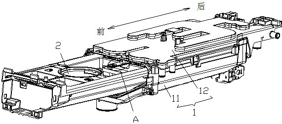
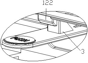
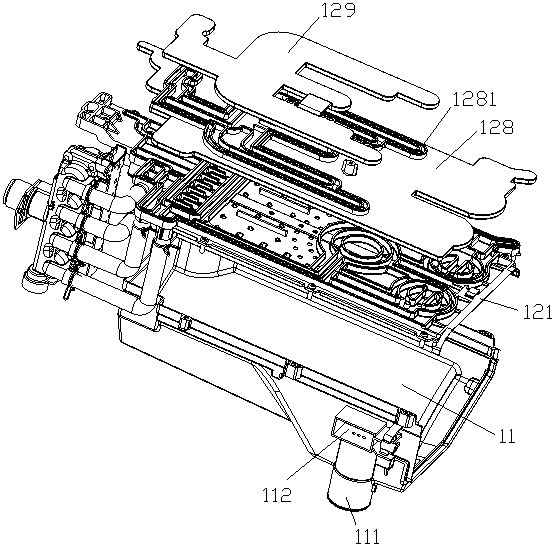
The invention provides a water storage tank for a washing machine and a washing machine. The water storage tank includes a water storage box fixed in the casing of the washing machine. The water storage box has a water storage box body and a water storage box fixed on the top of the water storage box body. The cover of the water box is provided with a condensation labyrinth on the cover of the water storage box. One end of the condensation labyrinth is provided with a vent hole connected to the outer cylinder of the washing machine, and the other end is provided with a vent hole connected to the body of the water storage box. connected hole. The condensation labyrinth can block the high-speed steam, reducing the speed of the steam. At the same time, it can also condense the steam, precipitate condensed water, and reduce the water content in the steam. In this way, the steam entering the condensation labyrinth from the vent hole, when it flows out from the communication hole The low-speed, low-temperature and dry gas enters the body of the water storage box; the precipitated condensed water also flows into the water storage box body through the communication hole; this ensures that the gas that finally overflows from the water storage tank is low-speed, low-temperature and dry gas, and the structure is relatively simple and reliable. High reliability and low manufacturing cost.

Description

technical field [0001] The invention belongs to the technical field of washing machines, and in particular relates to a water storage tank for a washing machine and a washing machine with the water storage tank. Background technique [0002] Existing drum washing machines generally have a water storage tank device, and the water storage tank can be used to ventilate and connect with the outer cylinder to ensure the air pressure balance between the cylinder and the outside. The ventilation position of the water storage tank is set at the rear. When the drum washing machine is running for drying or heating and washing at high temperature, hot and humid air will be ejected from the drum and enter the water storage tank. The speed is very fast, and it contains a lot of steam, causing water vapor to overflow the water storage tank. , Condensate into drops of water near the handle and display screen, thus affecting the appearance of the product and the life of the computer board. ...

Claims


Application Information

Patent Timeline
Patent Type & Authority Patents(China)
IPC IPC(8): D06F39/00
CPCD06F39/00
Inventor 梁启队李敬德黄本财黄涛
Owner QINGDAO HAIER WASHING ELECTRIC APPLIANCES CO LTD
Learn More