Flashlight

a flashlight and light source technology, applied in the field of flashlights, can solve the problems of wire slippage and the inability of flashlights to illuminate the desire place, and achieve the effect of extending the illumination rang

Inactive Publication Date: 2008-07-22
MOBILETRON ELECTRONICS
View PDF6 Cites 34 Cited by
  • Summary
  • Abstract
  • Description
  • Claims
  • Application Information

AI Technical Summary

Problems solved by technology

If there were no suitable place to hang the wire, the flashlight cannot illuminate the desire place.
Furthermore, the wire always slips because there is no device on the wire for hanging.

Method used


Image

  • Flashlight
  • Flashlight
  • Flashlight

Examples


Embodiment Construction

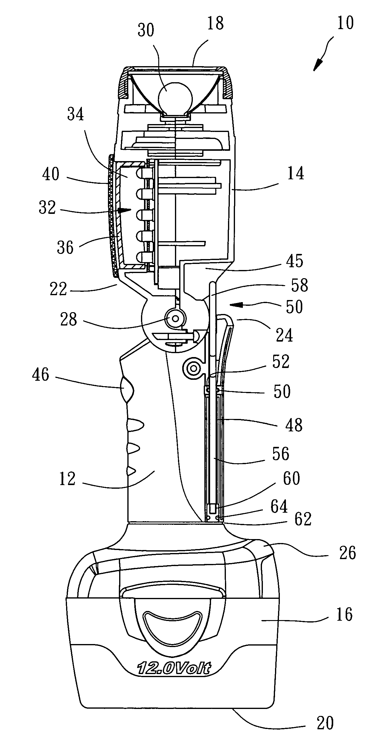
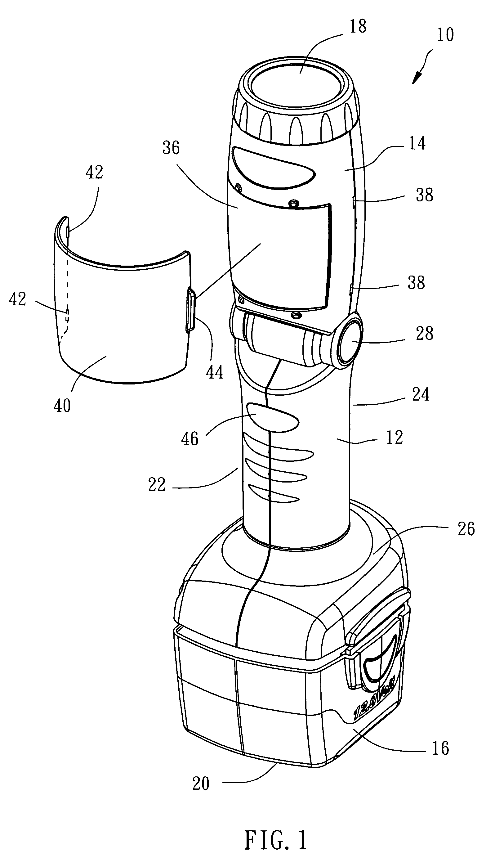
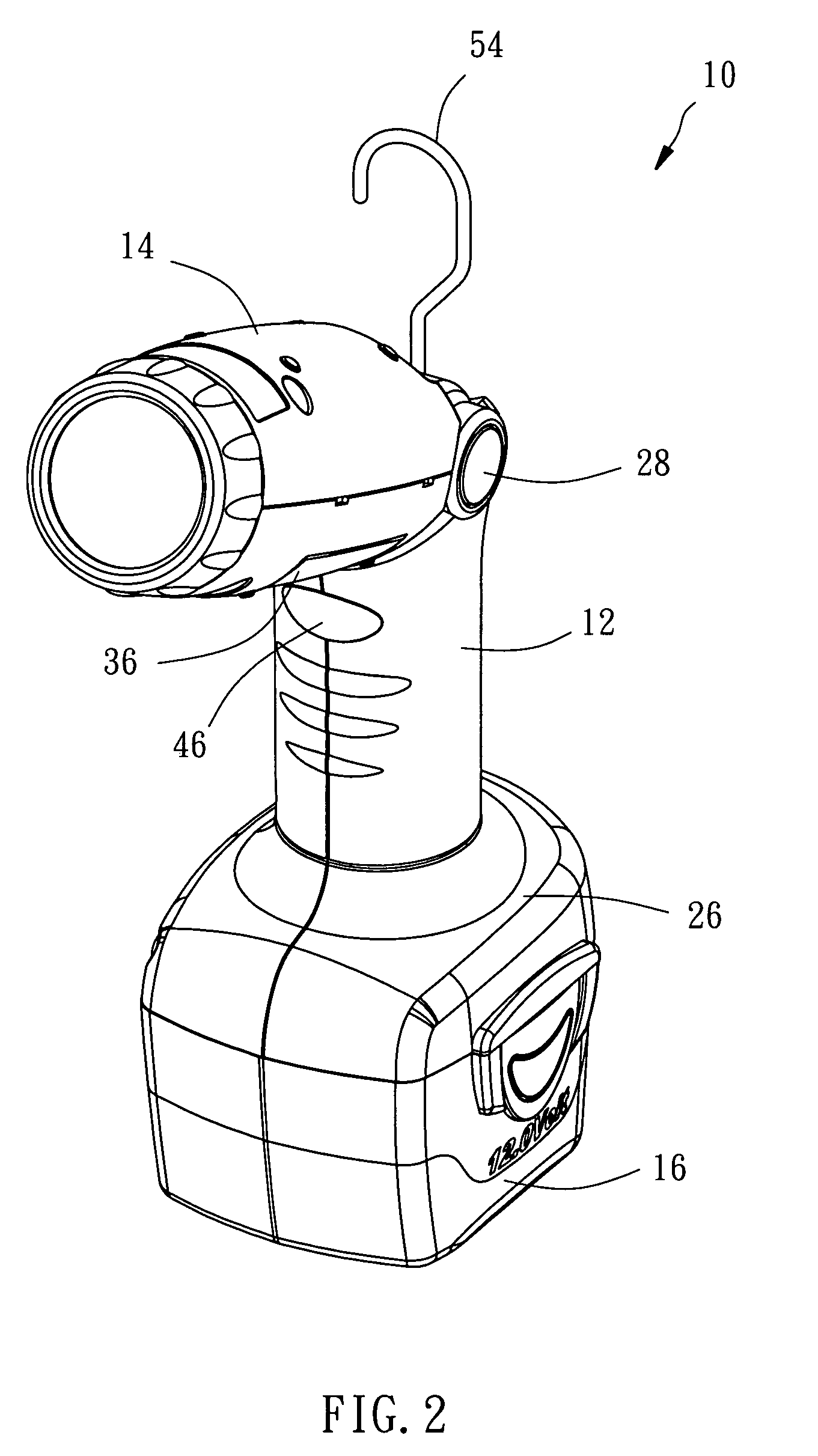
[0013]As shown in FIG. 1 and FIG. 2, a flashlight of the preferred embodiment of the present invention comprises:

[0014]A main member 10, which is consisted a base 12, a head 14 and a battery pack 16, has a top 18, a bottom 20, a front 22 and a rear 24. The base 12 has a connector portion 26 at an end thereof to be coupled with the battery pack 16. The battery pack 16 has rechargeable batteries therein and has a flat bottom at the bottom 20 of the main member 10, such that the main member 10 can stand on a surface.

[0015]The head 14 has an end pivoted on an end of the base 12, opposite to the battery pack 16, via a pivot 28, such that the head 14 can be flexed to the front 22 of the main member 10 about sixty degrees (FIG. 2 and FIG. 4). As shown in FIG. 3 and FIG. 4, the head 14 has a first light source 30 and a second light source 32. The first light source 30 has a light bulb at the top 18 of the head 14, and the second light source 32 includes five light emitting diodes (LEDs) in ...


PUM


Abstract

A flashlight includes a main member having top, a bottom, a front and a rear. The main member has a base a head and battery pack, wherein the head is pivoted on the base via a pivot to be flexed to the front. A first light source and a second light source are mounted on the head, wherein the second light source projects light that is substantially to that of the first light source. A hook is provided in a tunnel in the base to be drawn out or pushed into. The first and second light sources and the flexion of the head provide a greater illumination range and a function of adjusting the illuminating direction when it is hung.

Description

BACKGROUND OF THE INVENTION[0001]1. Field of the Invention[0002]The present invention relates generally to an illuminating device, and more particularly to a flashlight with greater illumination range and capable of changing the illuminating direction when it is hung.[0003]2. Description of the Related Art[0004]A conventional flashlight to illuminate narrow workplace includes a handle, a shell on an end of the handle, a wire with a plug on the other end of the handle and a light bulb in the shell. The shell includes a plate and a metallic net. The shell protects the light bulb and lets the light emitting out via the net. The flashlight usually is provided with a hook on the shell or on the handle, such that workers may hang the flashlight on a wall or other suitable place to work with both hands. As long as the flashlight is hung on a place, the orientation of illumination is fixed. To adjust the orientation of illumination of the flashlight, worker has to hang the wire on another p...

Claims


Application Information

Patent Timeline
Patent Type & Authority Patents(United States)
IPC IPC(8): F21L4/00F21L4/02F21V1/00
CPCF21L4/027F21L4/04F21V21/08F21V9/08F21L4/08F21L14/023F21Y2113/00F21V17/16F21Y2101/02F21Y2115/10
Inventor TENG, CHENG-IHUANG, YEN-CHIEH
Owner MOBILETRON ELECTRONICS
Why Eureka
Try Eureka