Casimir effect conversion

a technology of casimir and effect, applied in the direction of motor/generator/converter stopper, dynamo-electric converter control, instruments, etc., can solve the problems of not having been able to convert or extract net energy in these prior-art attempts, and much energy is needed to reset the plates

Active Publication Date: 2008-08-12
TYMES ADRIAN JEREMY
View PDF14 Cites 12 Cited by
  • Summary
  • Abstract
  • Description
  • Claims
  • Application Information

AI Technical Summary

Benefits of technology

[0004]The invention provides techniques in which a 1st force, field, or effect caused by a Casimir effect is converted into a 2nd force, field, or effect. The 1st force, field, or effect might be distinct from the 2nd force, field, or effect only in the net vector or might be distinct in other ways. For example, the distinction might involve substituting a torque for a linear force vec

Problems solved by technology

However, as much energy is needed to reset the plates by pulling the plates apart as can be extracted from movem

Method used


Image

  • Casimir effect conversion
  • Casimir effect conversion
  • Casimir effect conversion

Examples


Embodiment Construction

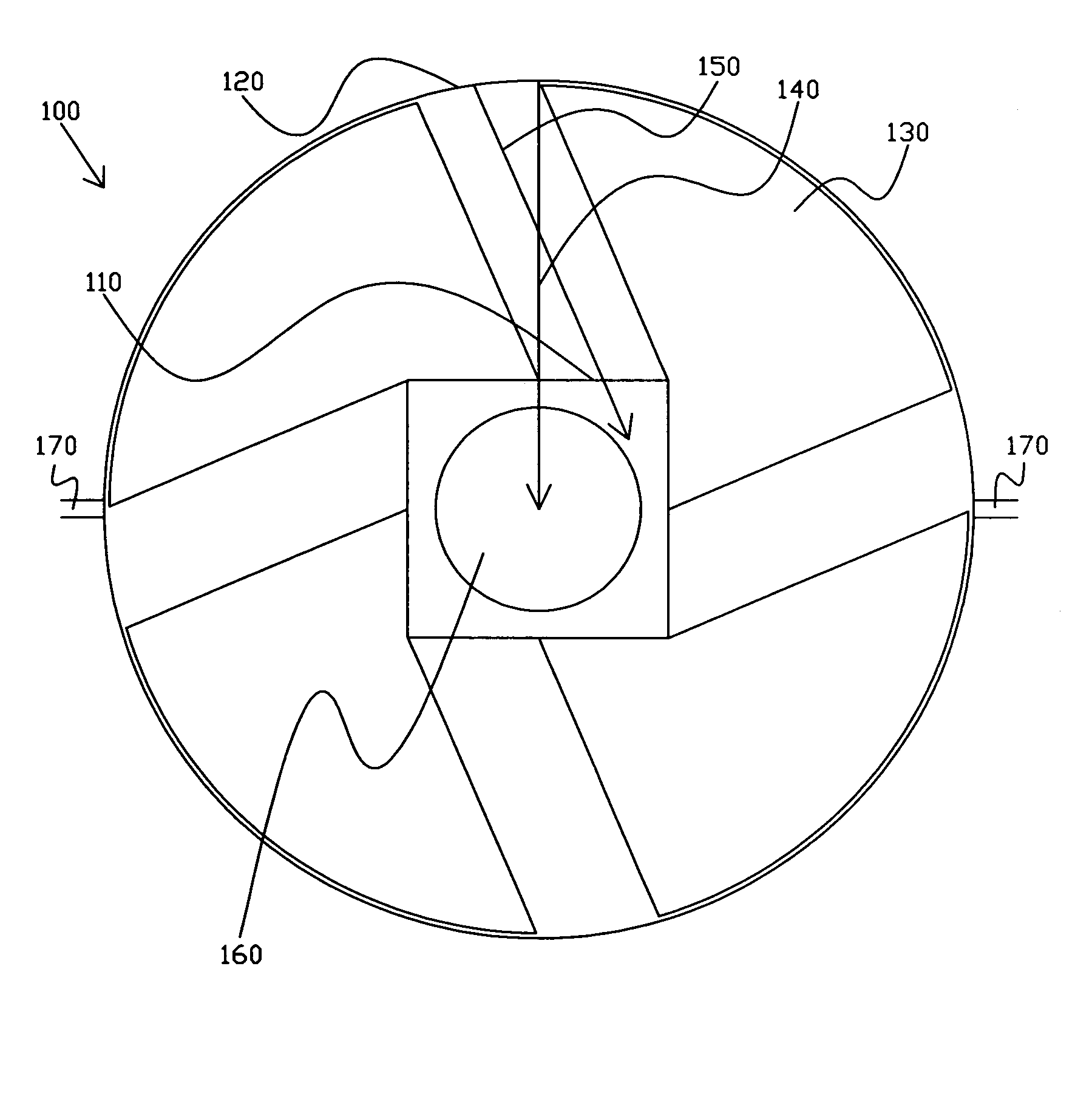
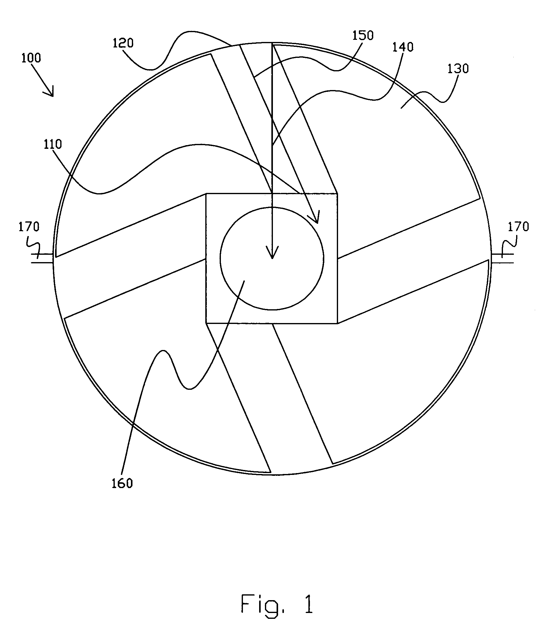
[0020]FIG. 1 shows a conceptual diagram of one embodiment of a device that uses the Casimir effect to generate, convert, or alter another force, field, or effect.

[0021]Briefly, one embodiment of the invention is an apparatus including at least a first structure and a second structure. The first structure is effective to generate a Casimir effect between at least portions thereof. The second structure is effective to alter or to convert the Casimir effect or a first type of force, field, or affect associated with the Casimir effect into a second type of force, field, or effect.

[0022]In more detail, device 100 in FIG. 1 includes two surfaces 110 and 120 of a first structure spaced apart by less than or equal to an effective distance of the Casimir effect. The inventor believes that this distance is on the order of tens of nanometers, with the strength of the Casimir effect falling off with the 4th power of distance. However, in the context of the invention, there is no particular requ...


PUM


Abstract

Techniques in which a 1st force, field, or effect caused by a Casimir effect is converted into a 2nd force, field, or effect. The 1st force, field, or effect might be distinct from the 2nd force, field, or effect only in the net vector or might be distinct in other ways. For example, the distinction might involve substituting a torque for a linear force vector or converting a force, field, or effect associated with the Casimir effect into movement or into an electric, magnetic, or electromagnetic force, field, or effect. These changes preferably are caused by an independent element placed proximate or between to the Casimir effect surfaces. Preferably, the torque causes rotation (i.e., spinning) of an element. This rotation is significantly different from prior-art embodiment because energy does not have to be put back into the system to “reset” the structures.

Description

CROSS REFERENCE TO RELATED APPLICATION[0001]The application claims priority from, and hereby incorporates by reference, U.S. Provisional Application No. 60 / 642,172, Generating a Torque from the Casimir Effect, filed Jan. 7, 2005, in the name of the same inventor, Express Mail No. EL 768 963 465 US.BACKGROUND OF THE INVENTION[0002]The Casimir effect is a known effect in physics, in which an attraction or repulsion exists between closely spaced objects. The Casimir effect is believed to be quantum mechanical in nature, as explained at Wolfram Scienceworld (Casimir Effect) (http: / / scienceworld.wolfram.com / physics / CasimirEffect.html), and in New Developments in the Casimir Effect, M. Bordag, U. Mohideen, and V. M. Mostepanenko, Elsevier Preprint (November 2005). This interpretation is disputed by some, cf., The Casimir Effect and the Quantum Vacuum, R. Jaffe, Phys. Rev. D72 (2005). While the Casimir effect has little effect on objects at human-scale, it has been precisely measured and i...

Claims


Application Information

Patent Timeline
IPC IPC(8): H02N11/00H02N1/00
CPCH02N11/008
Inventor TYMES, ADRIAN JEREMY
Owner TYMES ADRIAN JEREMY
Why Eureka
Try Eureka