Push switch

a push switch and push plate technology, applied in the direction of contact surface shape/structure, snap-action arrangement, contact, etc., can solve the problem of complicated to achieve the intended pressing load

Inactive Publication Date: 2008-09-30
PANASONIC CORP
View PDF7 Cites 83 Cited by
  • Summary
  • Abstract
  • Description
  • Claims
  • Application Information

AI Technical Summary

Benefits of technology

[0027]By means of this structure, the present invention offers a small and thin push switch with comfortable first-step and second-step tactile feedback, without causing an detrimental effect that may be caused by resilient deformation of the first movable contact on the tactile feedback produced by resilient deformation of the second movable contact.

Problems solved by technology

This makes it complicated to achieve the intended pressing load.

Method used


Image

  • Push switch
  • Push switch
  • Push switch

Examples


Embodiment Construction

[0042]A preferred embodiment of the present invention is described with reference to drawings.

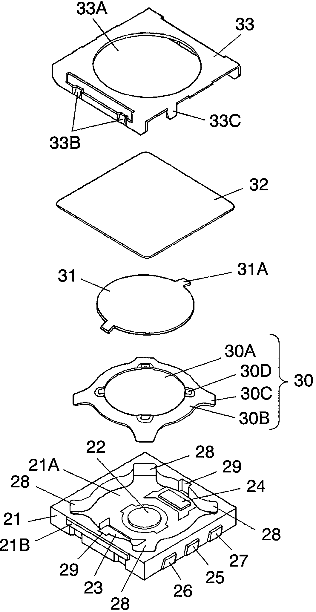
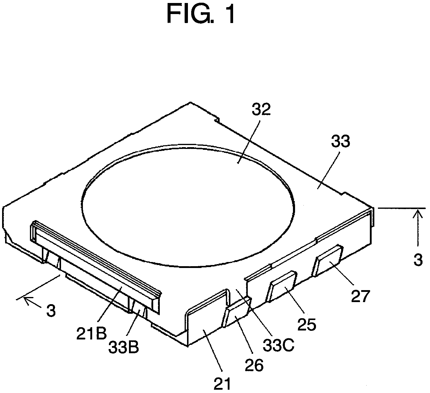
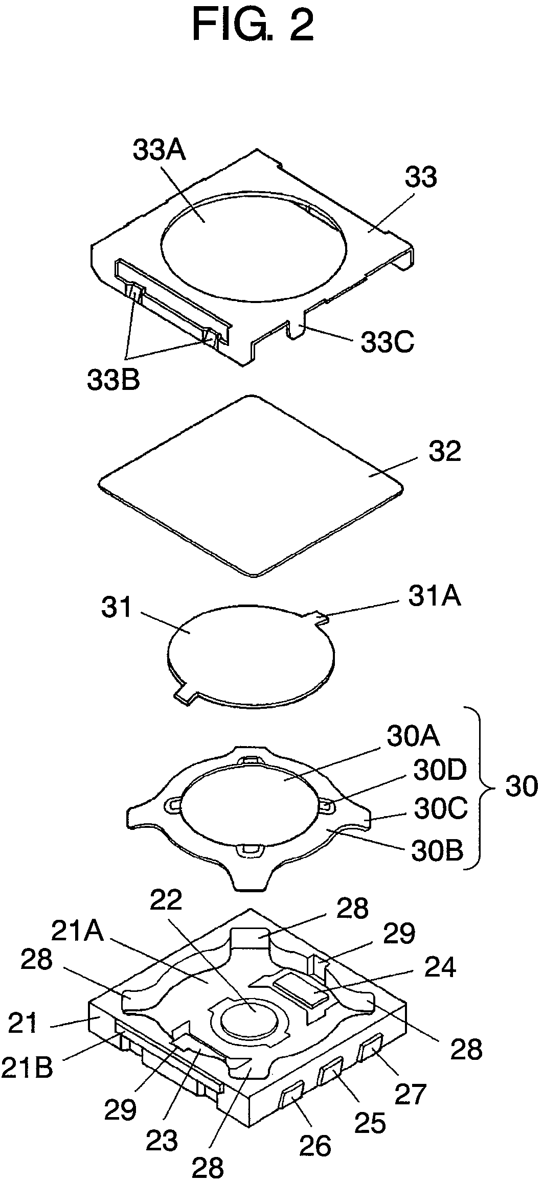
[0043]FIG. 1 is an outline view of a push switch in the preferred embodiment of the present invention. FIG. 2 is an exploded perspective view, and FIG. 3 is a sectional view taken along line 3-3 in FIG. 1. FIG. 4 is a sectional view taken along line 3-3 in FIG. 1, illustrating a first-step operation. FIG. 5 is a sectional view taken along line 3-3 in FIG. 1, illustrating a second-step operation. FIG. 6 is a chart of tactile curves.

[0044]In FIGS. 1 to 3, square switch case 21 made of insulating resin has substantially round recess 21A that has an open top. On an inner bottom face of this recess 21A, central fixed contact 22 is disposed at the center and independent peripheral fixed contacts 23 and 24 are disposed at two points symmetrical about central fixed contact 22. Second connecting terminal 25 electrically connected to central fixed contact 22 and first connecting terminals 26 and 27 e...


PUM


Abstract

A push switch which includes a switch case, a first movable contact, and a second movable contact. The switch case has a central fixed contact on an inner bottom face of its recess that has an open top, and a peripheral fixed contact. The first movable contact is curved protruding upward, and has a hole at its center. The first movable contact is disposed over the peripheral fixed contact with a space in between. The second movable contact is curved protruding upward, and is placed on the first movable contact. A pressing force for resiliently inverting the second movable contact is set greater than a pressing force for resiliently inverting the first movable contact; and two tactile feedbacks are produced by pressing from a side of the second movable contact.

Description

BACKGROUND OF THE INVENTION[0001]1. Field of the Invention[0002]The present invention relates to push switches employed as input units in a range of electronic devices, and more particularly to two-step push switches in which a first switch operates by a first push and a second switch operates by a further push.[0003]2. Background Art[0004]With electronic devices becoming increasingly smaller, components are also more densely packed inside. Push switches with two-step tactile feedback, which are employed in input units of these electronic devices, also need to become smaller and slimmer to save mounting space.[0005]A conventional push switch with two-step tactile feedback is described next with reference to FIGS. 8 to 14.[0006]FIG. 8 is an outline view of the conventional push switch. FIG. 9 is a sectional view taken along line 9-9 in FIG. 8, and FIG. 10 is a sectional view taken along line 10-10 in FIG. 8. FIG. 11 is a plan view of the conventional switch case. FIG. 12 is a section...

Claims


Application Information

Patent Timeline
Patent Type & Authority Patents(United States)
IPC IPC(8): H01H5/18
CPCH01H13/64H01H13/48
Inventor YANAI, YASUNORITOMAGO, TAKASHI
Owner PANASONIC CORP
Why Eureka
Try Eureka