Cable extending device

a cable extension and cable technology, applied in the direction of coupling device connection, color signal processing circuit, pulse technique, etc., can solve the problems of inability to effectively present, video signal cannot be correctly compensated, and cannot be stably transmitted, so as to simplify the structure of the cable extension unit, the effect of compensating attenuation and effective presentation

Inactive Publication Date: 2008-10-21
KOWA CO LTD
View PDF8 Cites 15 Cited by
  • Summary
  • Abstract
  • Description
  • Claims
  • Application Information

AI Technical Summary

Benefits of technology

[0013]According to this aspect of the invention, the attenuation compensation volume (e.g. GL, GH) of a video signal is computed on the basis of the attenuation of the pulses (PLAT) which are arranged in the digital sound signal (LRAT), and the attenuation of the video signal (RAT, GAT, BAT) is compensated on the basis of the computed attenuation compensation volume (e.g. GL, GH), so that the attenuation of the video signal (RAT, GAT, BAT) can be compensated without utilizing horizontal and vertical synchronous signals corresponding to the video signal as the signals for compensation. Then, the attenuation of the video signal can be correctly compensated irrespective of resolution of an image or kinds of displays, thereby stably compensating the attenuation. Besides, the sound signal is outputted to the signal receiver (3), so that effective presentation can be actualized by outputting sound to a video output machine as well as good videos.
[0014]Besides, the number of the signal lines (5A, 5B, 5C, 5D) also capable of transmitting sound signals to the signal receiver (3) does not increase since it is not necessary to transmit signals for compensation, separate from video signals, thereby simplifying the structure of the cable extension unit (1).
[0016]According to this aspect of the invention, the attenuation of the video signal (RAT, GAT, BAT) is compensated every frequency band (e.g. low frequency band and high frequency band), so that the attenuation of the video signal can be compensated according to attenuation factors which are different depending on frequencies. Therefore, the attenuation of the video signal can be accurately compensated, and better images can be displayed on a video output machine.
[0020]According to this aspect of the invention, the digital sound signal transmitting means (41, 43) outputs a digital modulation signal (LRDM) wherein pulses (PL0, PL1) of frequencies corresponding to digital data (DD) are arranged to the signal receiver (3), so that periodic pulses can be outputted to the signal receiver (3) irrespective of the presence of the pulse (pl) of the digital sound signal (LRD). Even if the digital sound signal (LRD) has no pulse (PL) (if Low state continues), the attenuation compensation volume (GL, GH) can be computed on the basis of the attenuation of the periodic pulses, so that the attenuation of the video signals (RAT, GAT, BAT) can be stably compensated.
[0022]According to this aspect of the invention, the attenuation of the video signal (RAT, GAT, BAT) is compensated every frequency band on the basis of the attenuation of the periodic pulses (PL0, PL1), so that the attenuation of the video signal (RAT, GAT, BAT) can be stably correctly compensated, and better videos can be stably displayed on a video output machine.

Problems solved by technology

But, a rectangular wave the waveform of which is predetermined can not stably transmitted, and a video signal can not be correctly compensated since the rectangular wave comprising a horizontal or a vertical synchronous signal changes in its pulse width or a cycle, depending on resolution of an image or kinds of displays.
In result, effective presentation may not be secured due to impossibility of stable compensation of video signals.

Method used


Image

  • Cable extending device
  • Cable extending device
  • Cable extending device

Examples


Embodiment Construction

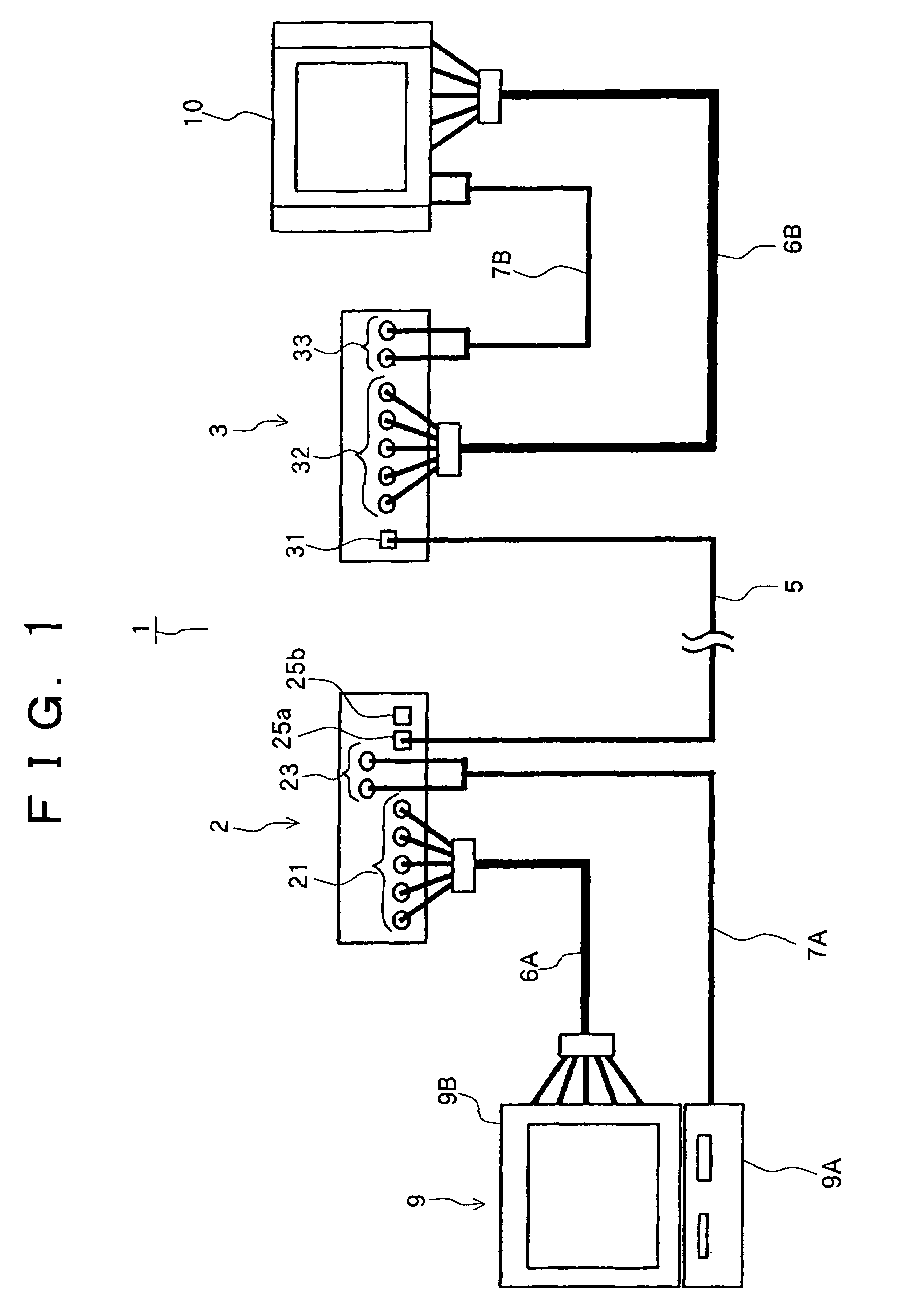
[0062]As shown in FIG. 1, a cable extension unit 1 has a signal transmitter 2 and a signal receiver 3, and the signal transmitter 2 can be connected with a cable through which video signals can be transmitted.

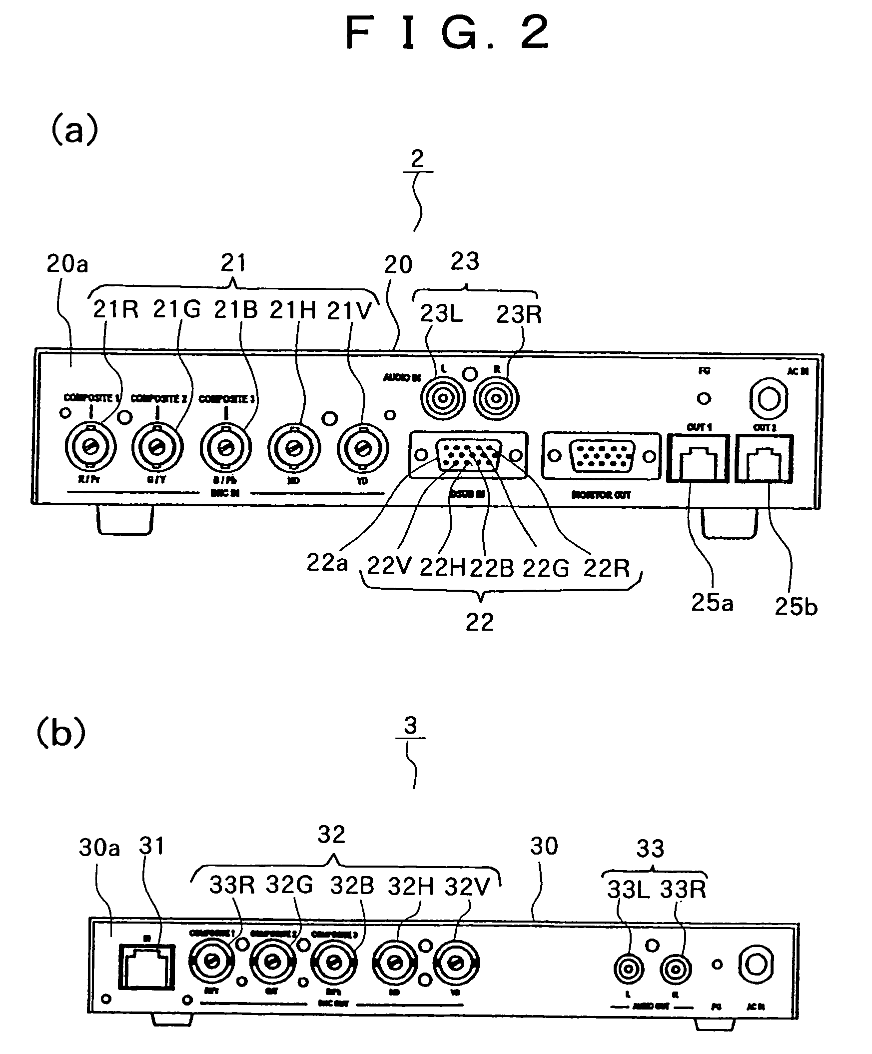
[0063]Video signals are RGB signals and component signals such as YPbPr signals and YCbCr signals (three signals comprised of a luminance signal and color difference signals). Cables for RGB signals are BNC (Bayonet Neill Concelman) cables each having a BNC connector (not shown) at each of both ends, and DSUB cables each having a DSUB connector (not shown) at each of both ends, and cables for component signals are BNC cables.

[0064]And, the signal transmitter 2 is freely connected with a cable through which sound signals can be transmitted. Sound signals are analog signals and digital signals. Analog signals are monaural signals and stereo signals. Cables for analog signals are RCA cables each having a RCA pin plug at each of both ends, for instance.

[0065]The signal transmitter ...


PUM


Abstract

Attenuation compensation volume computing means (60, 61, 62, 63, 67, 68, 69, 70) of a signal receiver computes attenuation compensation volume of a video signal (GL, GH) on the basis of attenuation of pulses which are arranged in a digital sound signal LRD from the signal transmitter, and video signal attenuation compensation means (60, 61) of the signal receiver compensates the attenuation of the video signal (RAT, GAT, BAT) on the basis of the computed attenuation compensation volume (GL, GH), thereby stably compensating the attenuation of the video signal irrespective of kinds of displays or resolution of an image, and outputting good sounds to a video output machine as well as good videos.

Description

TECHNICAL FIELD[0001]This invention relates to a cable extension unit for displaying videos from a video input source on a video output machine which is away from the video input source. In particular, the invention relates to a cable extension unit for stably compensating video signals by utilizing digital sound signals as signals for compensation and for outputting good videos and sounds to the video output machine, thereby actualizing effective presentation.BACKGROUND ART[0002]Such kind of a conventional known cable extension unit can compensate attenuation of transmitted video signals by utilizing rectangular waves comprising horizontal and vertical synchronous signals corresponding to video signals as signals for compensation. Such cable extension unit can display good videos compensated on a video output machine which is arranged at a separate place with no complicated structure of the cable extension unit since it is not necessary to transmit signals for compensation separate...

Claims


Application Information

Patent Timeline
Patent Type & Authority Patents(United States)
IPC IPC(8): H04N9/475H04N5/00H04N5/208H04N5/52H04N5/60H04N7/10H04N9/64H04N9/68H04N11/00
CPCH04B3/36H04N7/102H04N9/68H04N9/641H04N11/00
Inventor MORI, MASAFUMI
Owner KOWA CO LTD
Why Eureka
Try Eureka