Actuator and lens drive apparatus

a technology of actuators and lens drives, applied in the direction of electrical apparatus, piezoelectric/electrostrictive/magnetostrictive devices, piezoelectric/electrostriction/magnetostriction machines, etc., can solve the problem of difficult to effect drive control with stability

Inactive Publication Date: 2009-01-06
FUJI PHOTO OPTICAL CO LTD
View PDF14 Cites 0 Cited by
  • Summary
  • Abstract
  • Description
  • Claims
  • Application Information

AI Technical Summary

Benefits of technology

[0006]According to the actuator of the above (1), because the driving frictional member has a cross section of the driving frictional member orthogonal to a longitudinal direction thereof, the cross section changing in the longitudinal direction, the frictional force between the driving frictional member and the driven member varies in the axial direction (the longitudinal direction of the driving frictional member). Accordingly, the moving rate of and thrust to the driven member can be regulated in the longitudinal direction of the driving frictional member. This can suppress the moving rate of and thrust to the driven member from varying in the longitudinal direction of the driving frictional member, thus effecting a drive control with stability.
[0008]An actuator according to one aspect of the invention has a cross section orthogonal to an axis thereof (i.e., longitudinal direction of the driving frictional member), the cross section changing in an axial direction of the actuator. Accordingly, the driven member can be suppressed from varying in its moving distance, moving rate and thrust axially of the driving frictional member, thus effecting a drive control with stability.

Problems solved by technology

However, in the actuator of the background art, the moving rate of and thrust to the driven member changes depending upon the position of the driven member thus making it difficult to effect drive control with stability.

Method used


Image

  • Actuator and lens drive apparatus
  • Actuator and lens drive apparatus
  • Actuator and lens drive apparatus

Examples


Embodiment Construction

[0017]With reference to the accompanying drawings, description is now made in detail on an exemplary embodiment of an actuator according to the present invention.

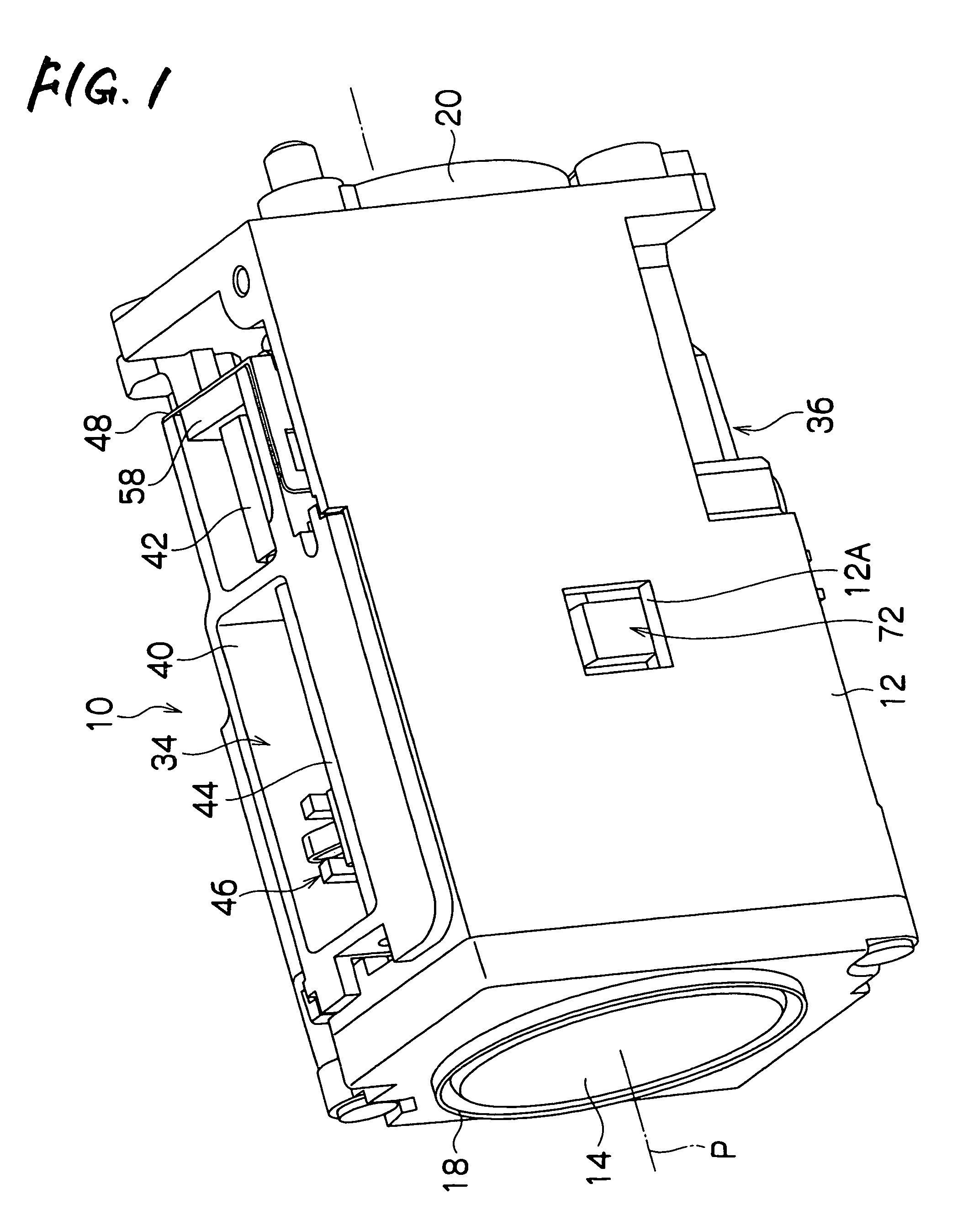
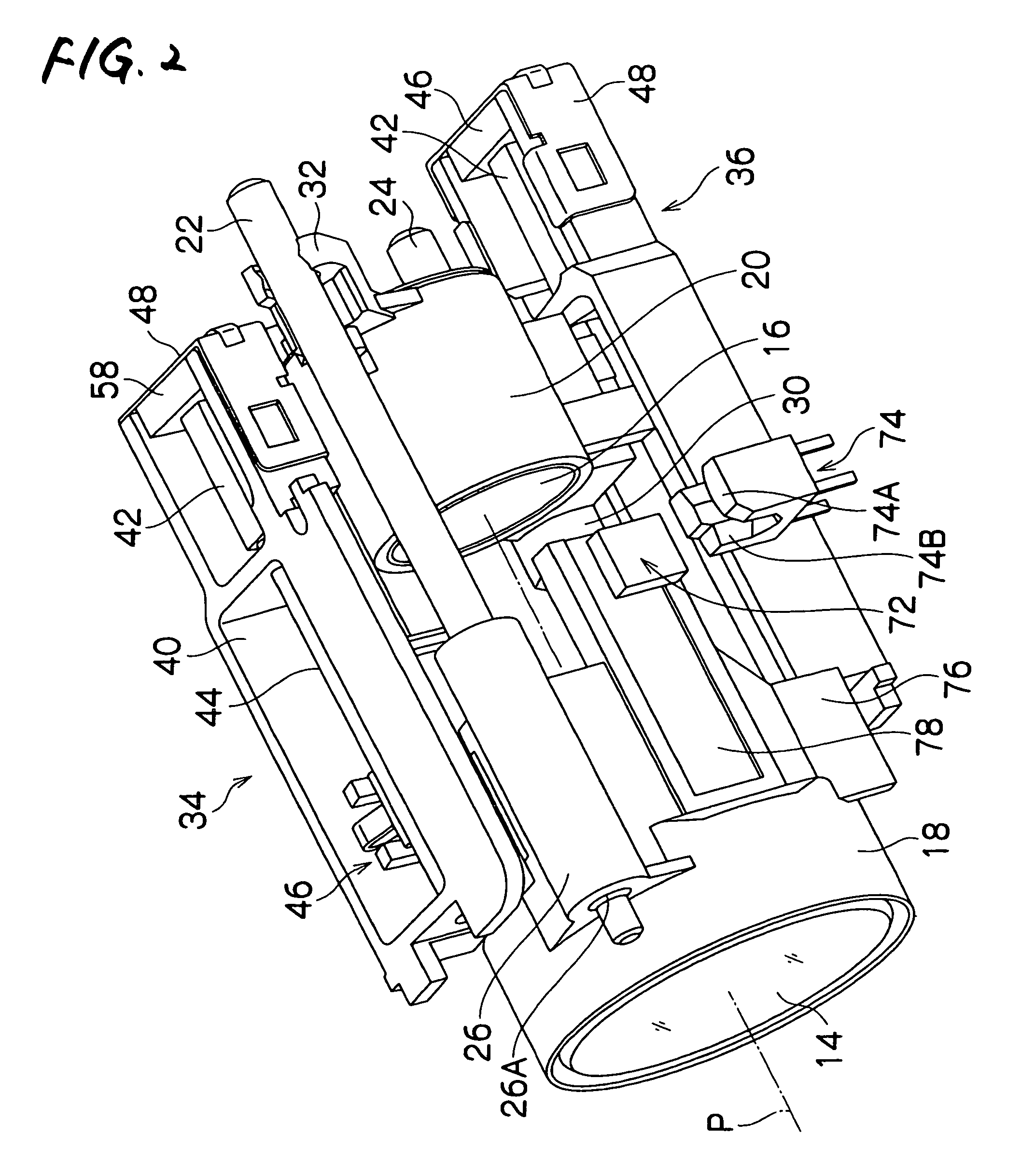
[0018]FIG. 1 is a perspective view showing a lens apparatus 10 to which is applied an actuator according to an aspect of the invention. FIGS. 2 and 3 are perspective views showing an internal arrangement of the same.

[0019]As shown in FIG. 1, the lens apparatus 10 has a body 12 formed nearly rectangular in form. The body 12 has therein zoom lenses (groups) 14, 16 that are shown in FIGS. 2 and 3. Of the zoom lenses (groups) 14, 16, one is provided as a variable power lens while the other is as a correction lens. The zoom lenses (groups) 14, 16 are respectively held in support frames 18, 20. The support frames 18, 20 are supported slidable in the direction of an optical axis P by two guide rods 22, 24. The two guide rods 22, 24 are arranged diagonal in the body 12 and parallel with the optical axis P, thus being fixed on the b...


PUM


Abstract

An actuator is provided and includes: an electro-mechanical conversion element; a driving frictional member attached at one end of the electromechanical conversion element with respect to a direction of expansion and contraction of the electromechanical conversion element; and a driven member frictionally engaged with the driving frictional member. The driving frictional member has a rod-like shape, and a cross section of the driving frictional member orthogonal to a longitudinal direction thereof is changed along the longitudinal direction.

Description

FIELD OF THE INVENTION[0001]The present invention relates to actuators, and more particularly to an actuator that is to be mounted on a small-sized precision apparatus, such as a digital camera or a cellular phone, and for driving a zoom lens.BACKGROUND OF THE INVENTION[0002]There is an actuator using a piezoelectric element as a driver for a lens unit of a digital camera or the like. For example, the actuator in Japanese Patent No. 2,633,066 has a piezoelectric element whose one end is secured to a drive shaft while the other end is fixed to an apparatus body. On the drive shaft, a lens barrel is slidably supported. The lens barrel is frictionally engaged with the drive shaft through utilization of a biasing force of a leaf spring. A drive pulse nearly in a saw-tooth form is applied to the piezoelectric element, to cause a deformation in the piezoelectric element at a rate different between an expansion and contraction directions thereof. For example, in case the piezoelectric elem...

Claims


Application Information

Patent Timeline
Patent Type & Authority Patents(United States)
IPC IPC(8): H01L41/08
CPCH02N2/025
Inventor SASAKI, RYOTA
Owner FUJI PHOTO OPTICAL CO LTD
Why Eureka
Try Eureka