Check patentability & draft patents in minutes with Patsnap Eureka AI!

Broadcast station, base station control device, receiver, control method, receiving method, broadcast system, reception program, transmission program, distribution program, and storage medium

a control device and content technology, applied in the field of broadcast stations, can solve the problems of abrupt deterioration of video and audio of the first contents data, and achieve the effects of reducing the process of transmitting or receiving, improving viewer satisfaction, and efficient use of communication channels

Inactive Publication Date: 2009-03-03
SHARP KK
View PDF29 Cites 22 Cited by
  • Summary
  • Abstract
  • Description
  • Claims
  • Application Information

AI Technical Summary

Benefits of technology

This approach enhances viewer satisfaction by maintaining video quality and reducing channel congestion, while minimizing the burden on both terminals by allowing efficient use of bidirectional channels and avoiding interruptions in video playback.

Problems solved by technology

However, due to the weak error tolerance, the videos and audios of the first contents data deteriorate abruptly when the characteristic value, indicative of the receiving condition, falls below the threshold.

Method used


Image

  • Broadcast station, base station control device, receiver, control method, receiving method, broadcast system, reception program, transmission program, distribution program, and storage medium
  • Broadcast station, base station control device, receiver, control method, receiving method, broadcast system, reception program, transmission program, distribution program, and storage medium
  • Broadcast station, base station control device, receiver, control method, receiving method, broadcast system, reception program, transmission program, distribution program, and storage medium

Examples


first embodiment

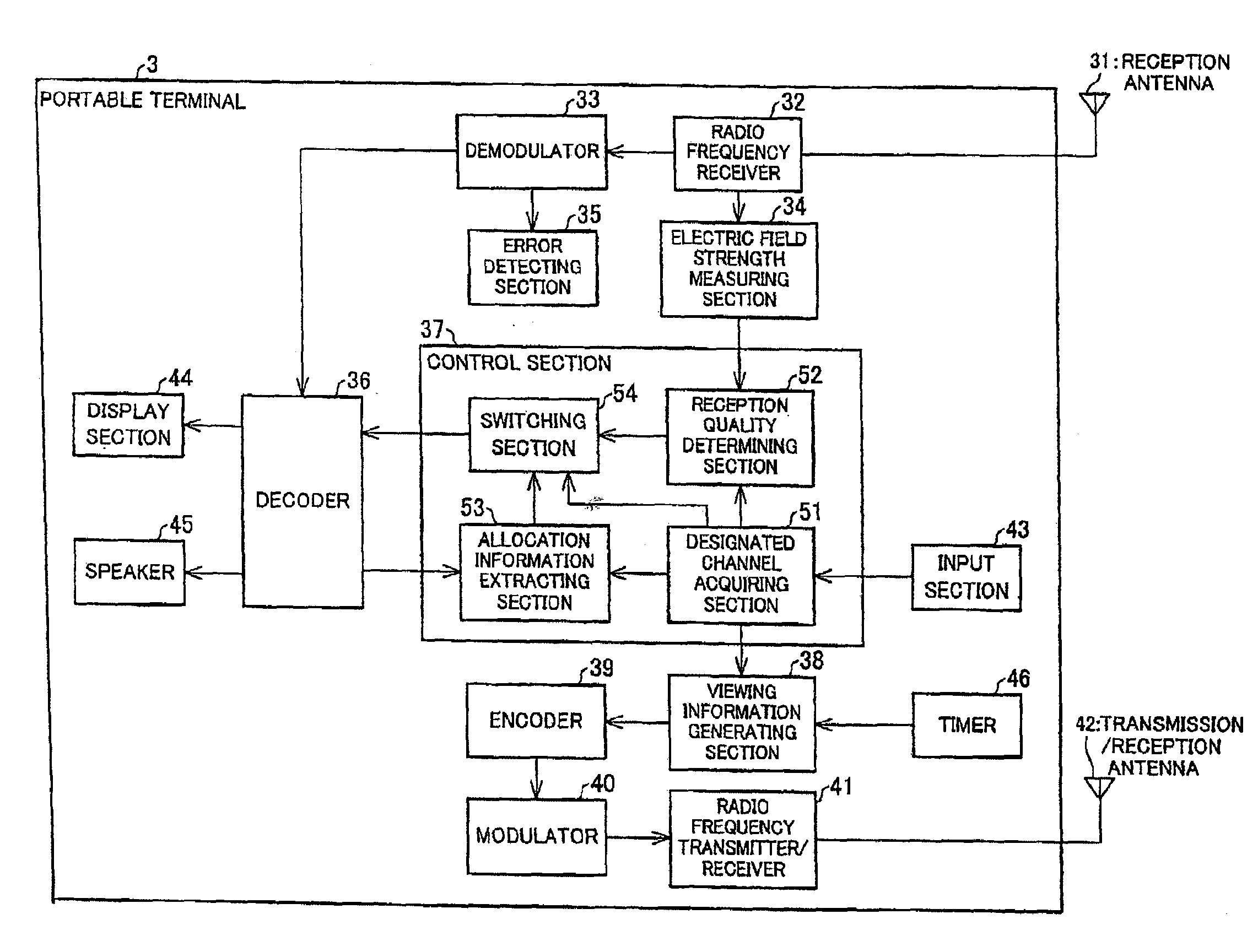
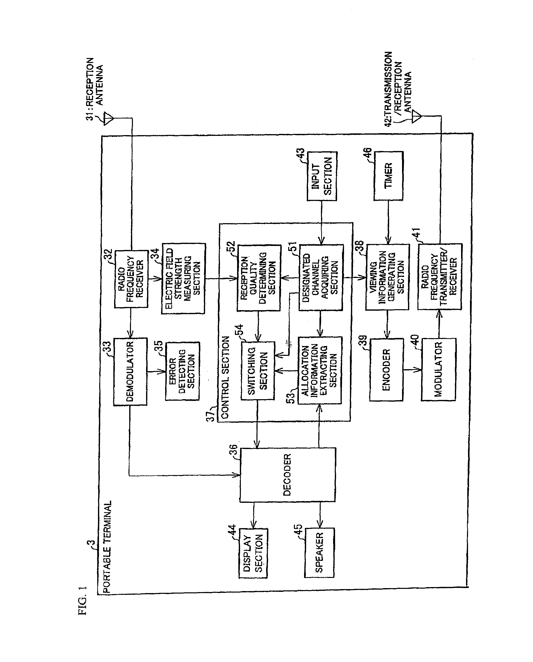
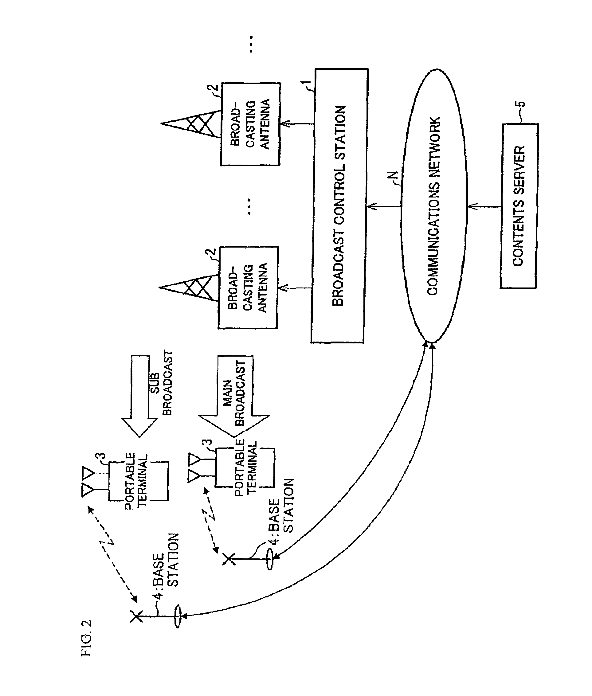
[0056]The following will describe one embodiment of the present invention with reference to FIG. 1 through FIG. 13. FIG. 2 is a block diagram illustrating a structure of a broadcast system according to one embodiment of the present invention. As shown in FIG. 2, the broadcast system includes a broadcast control station (broadcast station, control station) 1, a plurality of broadcasting antennas 2, a plurality of portable terminals (receivers) 3, a plurality of base stations 4, a contents server 5, and a communications network N.

[0057]The broadcast control station 1 obtains broadcast data from the contents server 5, and broadcasts a corresponding broadcasting signal of the data from the broadcasting antennas 2 for terrestrial digital TV broadcasting. In the present embodiment, the broadcast control station 1 is described to control broadcasting in each broadcast area, using the plurality of broadcasting antennas 2 installed in each broadcast area. However, the present invention is no...

second embodiment

[0178]The following will describe another embodiment of the present invention with reference to FIG. 14 through FIG. 17. Note that, for convenience of explanation, constituting elements having the same functions as those described in the foregoing First Embodiment are given the same reference numerals and explanations thereof are omitted.

[0179]As described in the First Embodiment, the broadcast control station 1 broadcasts the main broadcast data and sub broadcast data in parallel, using the broadcasting antennas 2. However, the sub broadcast data may be distributed by multicast broadcasting using other channels.

[0180]In the present embodiment, the base station 4 multicasts the sub broadcast data. FIG. 14 is a block diagram illustrating a structure of a broadcast system according to the present embodiment. As shown in FIG. 14, the broadcast system of the present embodiment differs from the First Embodiment in that it includes a broadcast control station 101 instead of the broadcast ...

third embodiment

[0215]As described in the First Embodiment, the portable terminal 3 generates viewing information and outputs it to the broadcast control station 1 irrespective of the current location. However, depending on the location where the broadcasting antenna 2 is installed, some areas are more likely to have the problem of poor reception quality (such areas will be referred to as monitored areas).

[0216]In the present embodiment, each portable terminal transmits viewing information to the broadcast control station 1 only when the portable terminal is in a monitored area. Thus, in the sub broadcast data deciding section 14 of the broadcast control station 1, each main broadcasting channel has been designated by a user, and the sub broadcast data deciding section 14 counts the number of portable terminals residing in the monitored areas. The sub broadcast deciding section 14 then decides, based on the result of counting, which sub broadcast data corresponding to which main broadcasting channe...


PUM


Abstract

A portable terminal includes: a radio frequency receiving section for receiving main broadcast data and sub broadcast data; an electric field strength measuring section for measuring an electric field strength corresponding to a receiving condition of the radio frequency receiving section; a reception quality determining section for determining reception quality based on a comparison between the electric field strength measured by the electric field strength measuring section and a predetermined threshold of required quality; a decoder, a display section, and a speaker for reproducing the main broadcast data or sub broadcast data; and a switching section for reproducing main broadcast data corresponding to a designated channel acquired by a designated channel acquiring section, when the reception quality determining section determines the reception quality to be good, and sub broadcast data corresponding to a designated channel acquired by the designated channel acquiring section, when the reception quality determining section determines the reception quality to be no good. With this arrangement, an operation of transmitting or receiving a retransmission request will not be required, and the communication channels can be used efficiently. As a result, customer satisfaction is improved.

Description

[0001]This nonprovisional application claims the benefit of U.S. provisional patent application filed on Sep. 8, 2005 with 60 / 714951, the entire contents of all of which are hereby incorporated by reference.FIELD OF THE INVENTION[0002]The present invention relates to a broadcast station for transmitting contents data, a base station control device for distributing contents data, and a receiver for receiving contents data.BACKGROUND OF THE INVENTION[0003]Conventionally, terrestrial digital television broadcasting and satellite broadcasting have been implemented using dedicated forward link channels. In a recently developed service, television programs or other contents are distributed to multiple terminals using multicast communications.[0004]Meanwhile, mobile terminals such as portable phones have been used as the receiving terminals of such broadcasts or distributions. A problem associated with such mobile terminals is that reception quality of the broadcast or distributed data var...

Claims


Application Information

Patent Timeline
Patent Type & Authority Patents(United States)
IPC IPC(8): H04J3/02H04W4/06H04W88/08
CPCH04L1/0045H04L1/08H04L1/20H04W4/06H04W88/08
Inventor KASHIWAGI, HIROKIMATSUBARA, GO
Owner SHARP KK
Features
  • R&D
  • Intellectual Property
  • Life Sciences
  • Materials
  • Tech Scout
  • Unparalleled Data Quality
  • Higher Quality Content
  • 60% Fewer Hallucinations
Learn More