Pads for mammography and methods for making and using them

a compression plate and mammography technology, applied in mammography, medical science, diagnostics, etc., can solve the problems of increasing discomfort, increasing the cost of x-ray procedures, and patient discomfort. significant, the effect of increasing the cos

Inactive Publication Date: 2009-03-17
BIOLUCENT LLC
View PDF52 Cites 42 Cited by
  • Summary
  • Abstract
  • Description
  • Claims
  • Application Information

AI Technical Summary

Benefits of technology

[0015]In addition, the apparatus may include a reusable frame or other device to which the base may be connected. For example, the frame may include at least a portion of a compression device, e.g., a compression paddle or bucky, that includes a window across which the base may be secured. The base and / or frame may include one or more connectors, e.g., mating tongues and grooves, that facilitate removably securing the base to the frame.
[0020]In accordance with another embodiment, a method is provided for performing mammography using a mammography unit including a compression plate, the compression plate including an opening within an x-ray field of the mammography unit. A radiolucent cushioning element may be connected to the compression plate across the window, a breast may be compressed using the cushioning element, the cushioning element deforming under forces applied during compression to provide comfort, and a mammogram may be obtained of the compressed breast.

Problems solved by technology

One of the problems with mammography is that the patient may experience significant discomfort during compression of the breast.
However, with greater compression comes increased discomfort.
Disposing of the entire x-ray sleeve after a single use, however, may increase the cost of x-ray procedures.

Method used


Image

  • Pads for mammography and methods for making and using them
  • Pads for mammography and methods for making and using them
  • Pads for mammography and methods for making and using them

Examples


Embodiment Construction

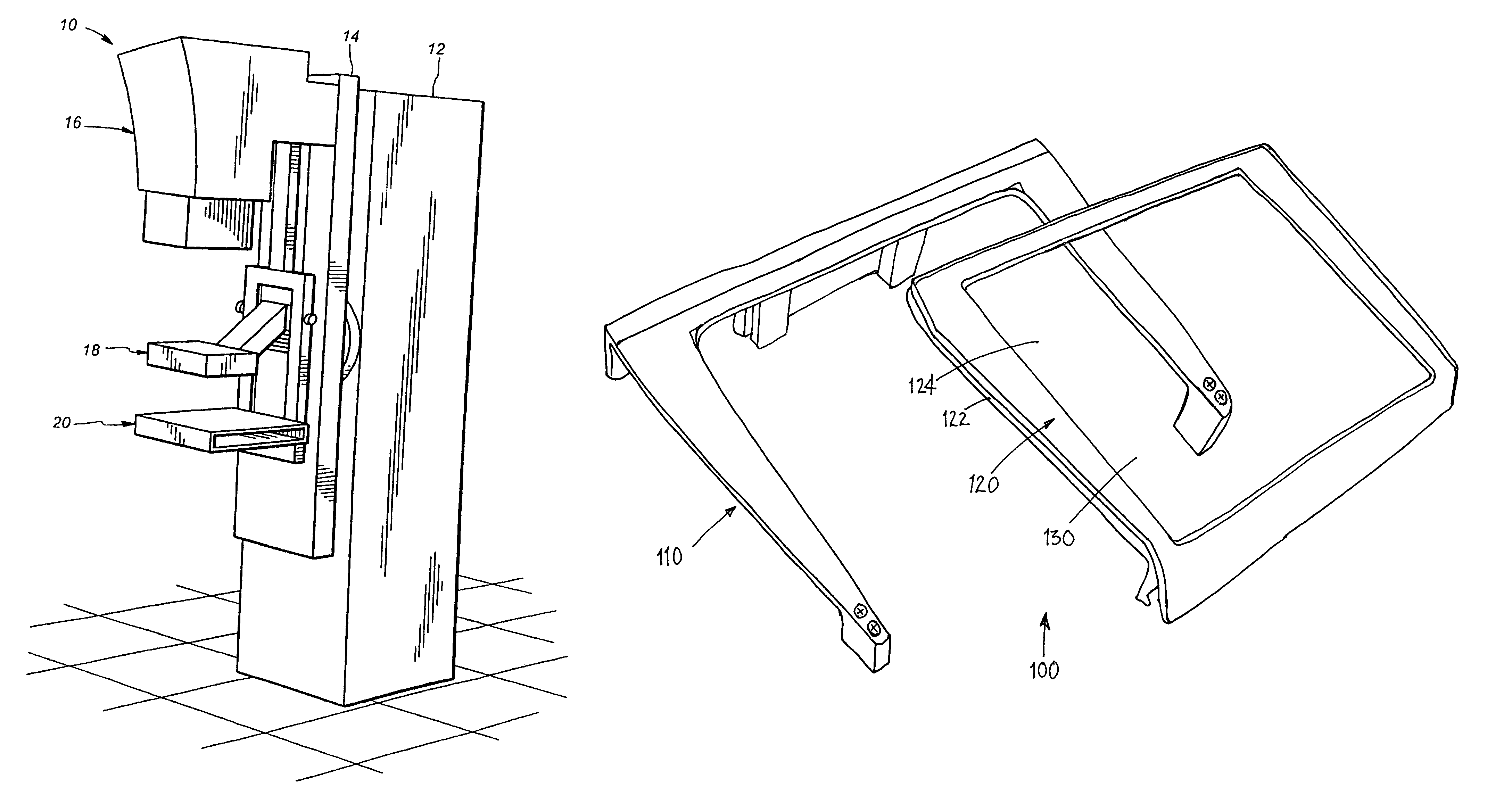
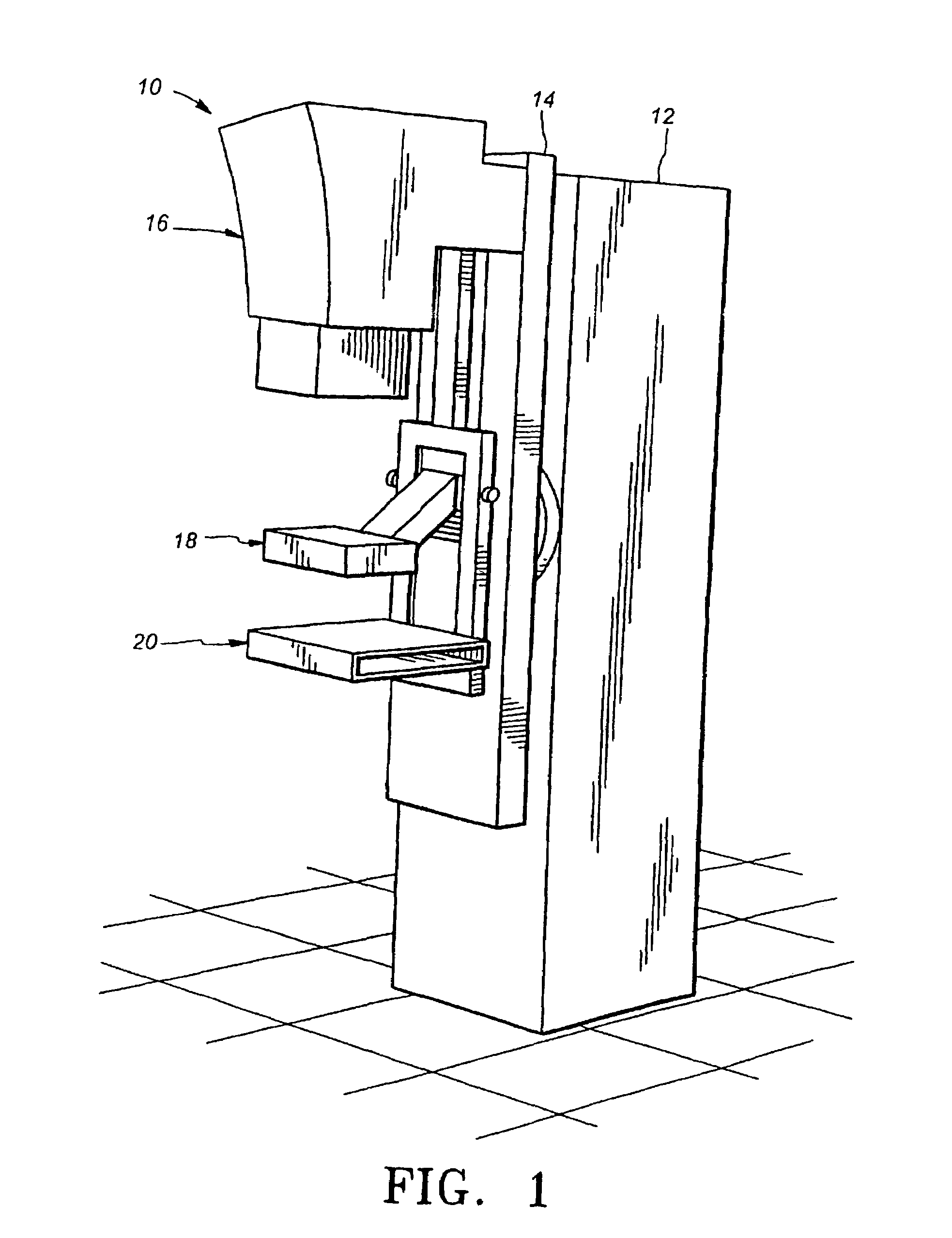
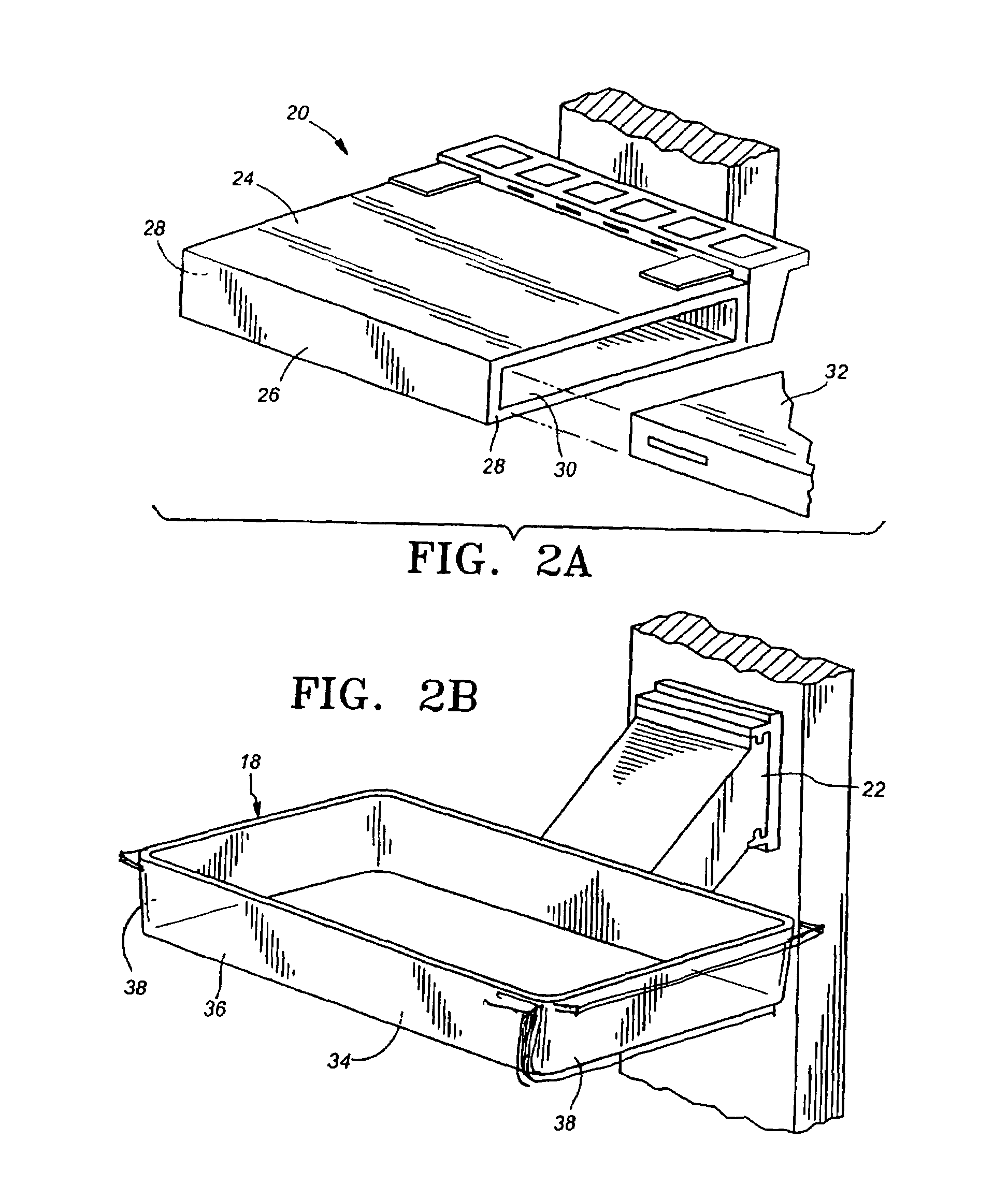
[0034]Turning to FIGS. 3-6, an exemplary embodiment of a device 100 is shown for cushioning a compression surface of an x-ray device, such as the mammography unit 10 of FIG. 1. In the configuration shown, the cushioning device 100 may be mounted or otherwise placed on or over an x-ray plate, such as the bucky 20 shown in FIG. 2A. It will be appreciated that the cushioning device 100 may be used in conjunction with other compression devices (not shown).

[0035]Generally, the cushioning device 100 includes a frame 110 that may be mounted on or adjacent a compression device (not shown) and a pad device 120 that may be connected to the frame 110. Optionally, one or more disposable covers 130 may be provided on the pad device 120, as described further below. In the exemplary embodiment shown in FIG. 3, the frame 110 may include a back panel 112, and opposing side panels 114 extending from opposite ends of the back panel 112 to define a window or opening 116 therebetween.

[0036]The frame 110...


PUM


Abstract

A compression device includes a frame mountable to a mammography unit that includes a window disposed within an x-ray field of the mammography unit when the frame is mounted to the mammography unit, and a radiolucent compressible member connectable to the frame across the window for providing a compression surface within the x-ray field. For example, the compressible member may include a rigid backing member and a radiolucent pad, e.g., a gel pad, on the backing member. The backing member and frame may include tongue and groove or other connectors for connecting the compressible member to the frame. Optionally, one or more thin, radiolucent films may be removable from the compressible member, e.g., after obtaining x-rays from successive individual patients.

Description

[0001]The present application claims benefit of application Ser. No. 60 / 624,683, filed Nov. 2, 2004, the entire disclosure of which is expressly incorporated by reference herein.FIELD OF THE INVENTION[0002]The present invention relates generally to compression devices for mammography or other x-ray procedures and methods for using such compression devices, and more particularly to devices and methods for cushioning or padding surfaces of compression plates applied to body parts during x-ray procedures, for example, during mammography, biopsies, and the like.BACKGROUND[0003]During mammography, a patient's breast is placed under compression by opposing plates attached to a mammography unit. Once under compression, an x-ray may be taken to determine the presence or absence of suspect lesions in the breast tissue, e.g., calcifications or tumors. An important reason for compressing the breast during mammography is to provide a thinner cross-section of tissue for the x-rays to pass throug...

Claims


Application Information

Patent Timeline
Patent Type & Authority Patents(United States)
IPC IPC(8): A61B6/04
CPCA61B6/0414G03B42/04A61B6/502
Inventor HERMANN, GEORGE D.LEBOVIC, GAIL S.
Owner BIOLUCENT LLC
Why Eureka
Try Eureka