
Golf club heads

a golf club and club head technology, applied in the field of golf club heads, can solve the problems of complex engineering principles and material science involved in golf club design, and achieve the effect of increasing the speed of the club head and strengthening the hitting position

Inactive Publication Date: 2009-04-07
BELMONT PETER ANGELO
View PDF8 Cites 62 Cited by
  • Summary
  • Abstract
  • Description
  • Claims
  • Application Information

AI Technical Summary

Problems solved by technology

The complexity of the engineering principles and material science involved in golf club designs are well known.

Method used


Image

  • Golf club heads
  • Golf club heads
  • Golf club heads

Examples


example 1

[0065]The following golf club heads were designed and fabricated: iron heads Nos. 3, 4, 5, 6, 7, 8, 9, pitching wedge, sand wedge and lob wedge; fairway woods Nos. 3, 5 and 7; and a driver. The irons and fairway woods were made from stainless steel and the driver was made from titanium. The irons were made in three pieces from a front face mold, a rear face mold, and a hosel mold and welded together. Irons were polished and surface treated to provide horizontal score lines and a standard centralized burnished-like front face hitting area. Score lines do not exceed 35 / 1000 inch.

[0066]The fairway woods and driver were conventionally molded and fabricated with a hollow interior section. The fabricated iron heads are illustrated in FIGS. 11A-11J. The fabricated fairway woods are illustrated in FIGS. 12-14.

[0067]The center of gravity of the irons of FIGS. 11A-11J were determined and illustrated in relation to the location from the face center of the club heads. It can be seen that while ...


PUM


Abstract

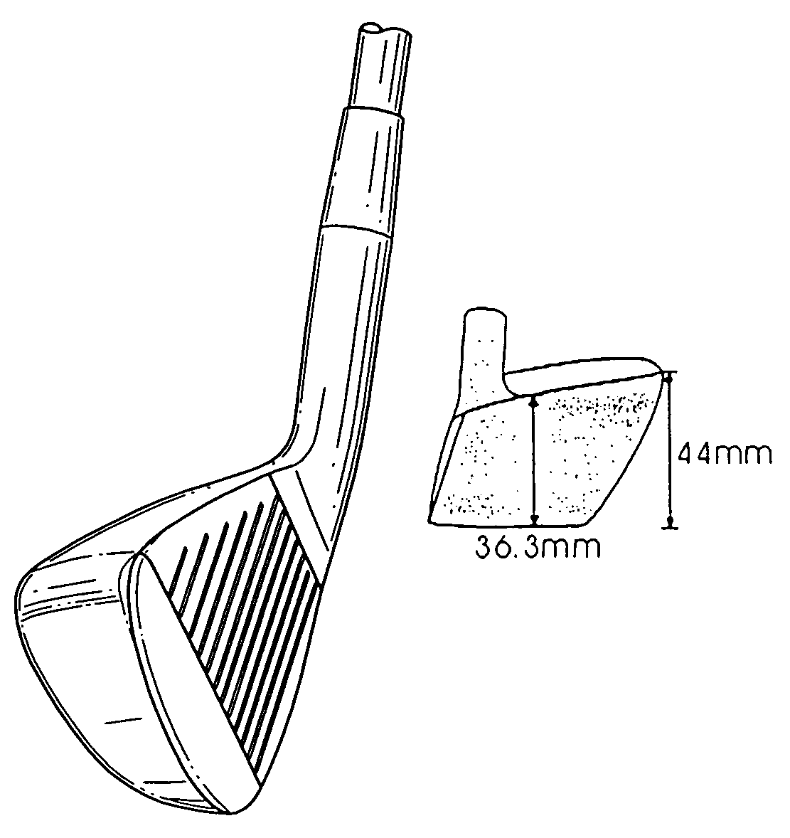
Golf club heads are described. The present invention is directed to golf club heads that have a thicker and heavier top line region and a thinner and lighter sole region than conventional designs. The novel golf club heads of the invention have a low tendency to get stuck in turf, change the face angle upon impact providing a stronger hitting position, increase the club head speed, and provide straighter and increased flight distance. Golf club irons, fairway woods, and driver are provided.

Description

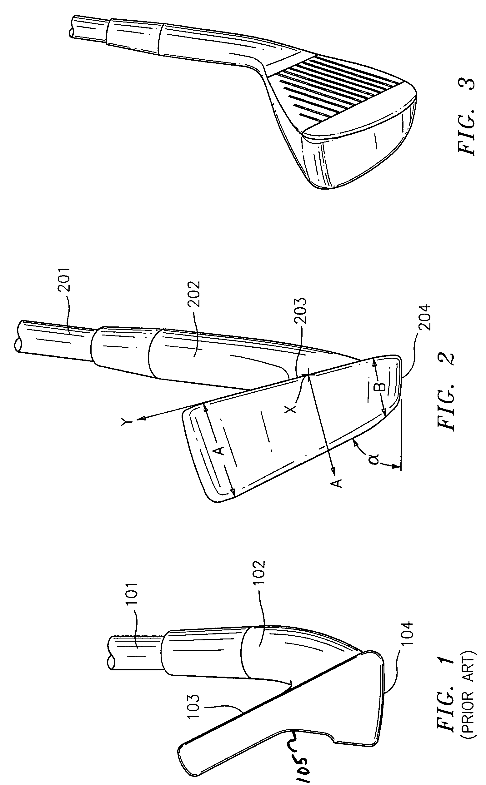
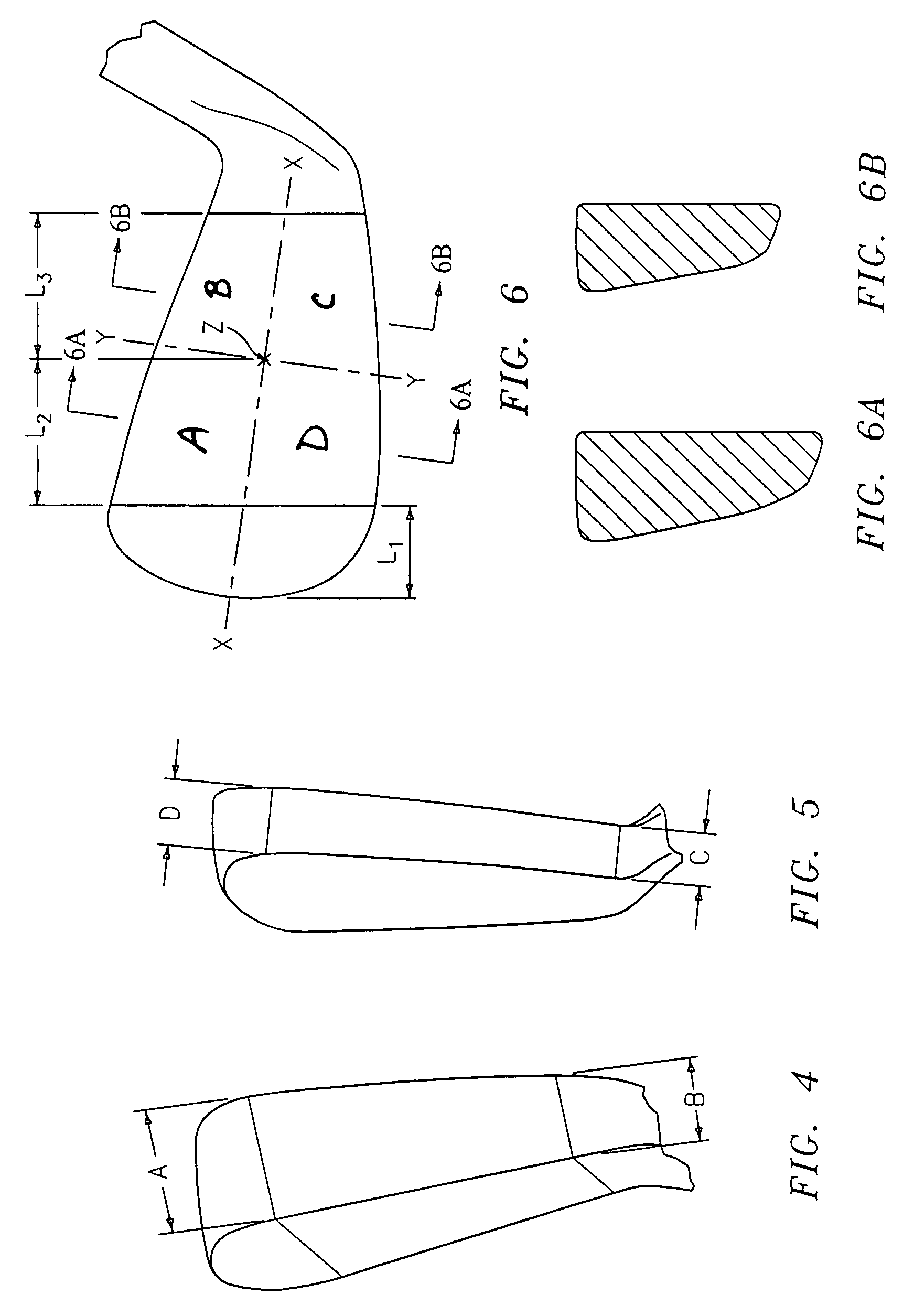
[0001]This application claims priority from U.S. Provisional Application No. 60 / 739,365 filed Nov. 23, 2005.BACKGROUND OF THE INVENTION[0002]1. Field of the Invention[0003]The present invention relates to golf club heads. More specifically, the invention relates to golf club heads that are top-head-weighted and aerodynamic shape. The invention describes various embodiments. The preferred embodiments describe a thicker and heavier top line region of club heads that taper along the vertical axis to a thinner bottom or sole line and also taper along the horizontal axis from a thinner heel to a thicker toe region.[0004]2. Description of the Prior Art[0005]By way of background, there are many variations of golf club designs, including drivers, irons and putters. The complexity of the engineering principles and material science involved in golf club designs are well known. The choice of materials and design for each component of a golf club (i.e., head, shaft, hosel, grip etc.) influence ...

Claims


Application Information

Patent Timeline
Patent Type & Authority Patents(United States)
IPC IPC(8): A63B53/04
CPCA63B53/0466A63B53/047A63B2053/005A63B2053/0408A63B2053/0433A63B2053/0445A63B2225/01A63B53/0408A63B53/005A63B53/0433A63B53/0445
Inventor BELMONT, PETER ANGELO
Owner BELMONT PETER ANGELO
Learn More