Drum type washing machine

a drum type and washing machine technology, applied in the direction of washing machine with receptacles, magnetic circuit shape/form/construction, cleaning using liquids, etc., can solve the problems of poor washing performance, poor formability, heavyness, etc., to reduce material and weight, simplify the fabrication process, and facilitate assembly

Active Publication Date: 2009-04-21
LG ELECTRONICS INC
View PDF25 Cites 54 Cited by
  • Summary
  • Abstract
  • Description
  • Claims
  • Application Information

AI Technical Summary

Benefits of technology

[0034]An object of the present invention is to provide a stator structure which can reduce material and weight required in fabrication of a stator of a BLDC motor, simplifies a fabrication process, and enables secure mounting of the stator to a mating part, such as a tub.
[0035]Another object of the present invention is to provide a structure which can sustain weight and vibration of a motor from a side of the tub in a case a washing machine BLDC motor is attached to a wall surface of the tub directly, which BLDC motor has 1.5 kg or more stator weight, and rotates at a speed varied in a range of 600˜2,000 RPM.
[0036]Another object of the present invention is to provide a structure which enables easy assembly when a stator and the tub are assembled in an assembly line.
[0037]Another object of the present invention is to provide a driving unit structure which enables a service man to make easier service at a time of maintenance and replacement of a product.

Problems solved by technology

In summary, transmitting driving force from the motor 5a to the drum 3 through the motor pulley, the drum pulley, and the belt indirectly, the related art drum type washing machine is liable to cause faults, and noise, has many energy wasting factors, and results in poor washing performance.
Along with this, because of the tub 2 formed of stainless steel, the related art drum type washing machine is expensive, has a poor formability, and is heavy.
However, since the direct coupling type drum type washing machines with BLDC motors developed up to the present time still has various disadvantages and problems in view of structures, process lines, or operations, there are requirements for direct coupling type drum type washing machines of new structures.
That is, the related art drum type washing machine has much waste of materials, such as core, and so on, in fabrication of the motor, or has a problem of complicate fabrication process, and strengths of the tub or the stator mounted thereon are weak for mounting the motor on the tub, to fail in attenuating vibration and noise, effectively.
That is, in a case of a drum type washing machine which employs a BLDC motor with a stator secured to a rear wall of the tub, since an axis direction of the stator is substantially parallel to a floor, vibration caused at the time of operation of the washing machine causes heavy damage at the joining portion of the stator with the tub rear wall.
However, fabrication of above SC (Sectional type core) of the stator, not only is complicate, but also has waste of much material.
For reducing waste of material, and simplifying the fabrication process, though so called helical type core is favorable, in which a steel plate having the Ts and the base is stacked while turning the steel plate in an helix, the helical type core has disadvantage in that the projections 500 can not be formed toward an inner side of the core for joining the stator to the tub because a steel plate punched in a form of a stripe is required to be bent in a helix in fabrication of the helical type core.
This is because the projections 500 formed toward an inner side of the core make the stacking of the core by the turning the core in a helix impossible due to too great width of the core.
That is, in a case of a drum type washing machine which employs a BLDC motor with a stator secured to a rear wall of the tub, since an axis direction of the stator is substantially parallel to a floor, vibration caused at the time of operation of the washing machine causes heavy damage at the joining portion of the stator 6 with the tub rear wall.
Moreover, when an axis direction of the stator is parallel to the ground, with a heavy stator over 1.5 kg overhung therefrom, there has been breakage of a portion of the tub the stator is fastened thereto caused by the vibration.

Method used


Image

  • Drum type washing machine
  • Drum type washing machine
  • Drum type washing machine

Examples


Embodiment Construction

[0058]Reference will now be made in detail to the preferred embodiments of the present invention, examples of which are illustrated in the accompanying drawings FIGS. 3˜11. Wherever possible, the same reference numbers will be used throughout the drawings to refer to the same or like parts.

[0059]A first preferred embodiment of the present invention will be described with reference to FIGS. 3˜7.

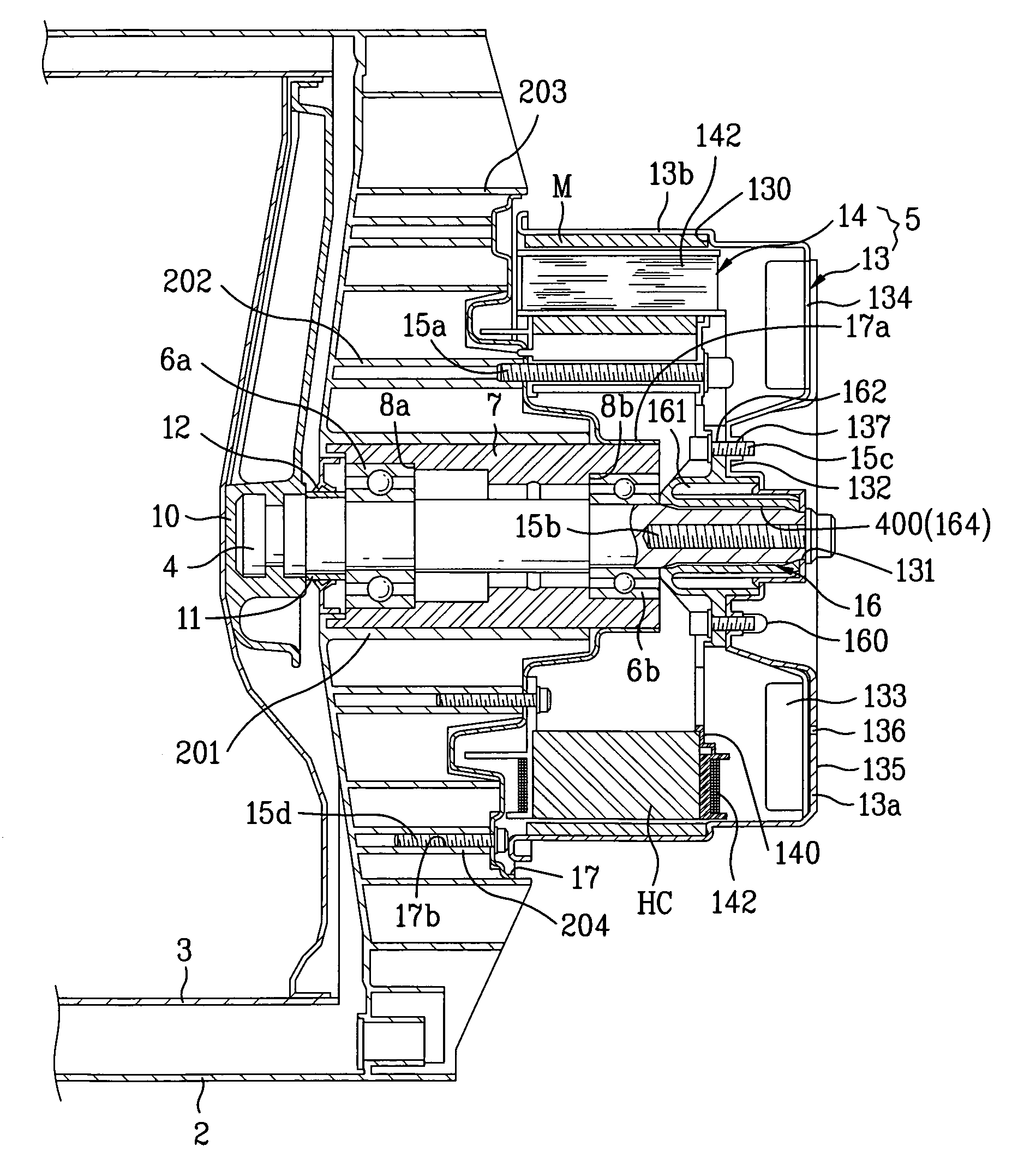
[0060]FIG. 3 illustrates a longitudinal section of a drum type washing machine in accordance with a preferred embodiment of the present invention, and FIG. 4 illustrates a longitudinal section of an “A” part in FIG. 3, showing a detail of a driving unit of a drum type washing machine in accordance with a preferred embodiment of the present invention.

[0061]FIG. 5 illustrates a perspective view of the stator in FIG. 4, FIGS. 6A and 6B illustrate enlarged views of key parts of FIG. 4, wherein FIG. 6A illustrates a plan view of the key parts, and FIG. 6B illustrates a perspective view of the key p...


PUM

PropertyMeasurementUnit
weightaaaaaaaaaa
driving forceaaaaaaaaaa
electrical insulationaaaaaaaaaa

Abstract

In one aspect, a drum type washing machine includes, among other things, a tub supporter of metal between a wall of a tub and a stator, where the stator includes an annular helical type core having multiple layers formed by winding a steel plate having Ts and a base portion in a helix starting from a bottom layer to a top layer, an insulator insert molded with the helical type core to cover an outside surface of the helical type core for electrical insulation of the helical type core, and three fastening portions formed, as a unit with the insulator projected from an inside circumferential surface of the helical type core toward a center of the stator, for fastening the stator to the tub supporter, wherein the fastening portion has a fastening hole at a center for fastening the stator to the wall of the tub with screws.

Description

CROSS-REFERENCE TO RELATED APPLICATIONS[0001]This application claims the benefit of Korean Application No. P2003-00789481 filed on Nov. 6, 2003, which is hereby incorporated by reference as if fully set forth herein.BACKGROUND OF THE INVENTION[0002]1. Field of the Invention[0003]The present invention relates to drum type washing machines, and more particularly, to a structure of driving part of a direct coupling type drum type washing machine.[0004]2. Discussion of the Related Art[0005]In general, in a drum type washing, the washing is performed by using friction between a drum rotated by driving force of a motor and laundry in a state detergent, washing water, and the laundry are introduced into the drum, and gives almost no damage to the laundry, has no entangling of the laundry, and can provide a pounding, and rubbing washing effect.[0006]A related art drum type washing machine will be described briefly with reference to FIG. 1.[0007]FIG. 1 illustrates a longitudinal section of a...

Claims


Application Information

Patent Timeline
Patent Type & Authority Patents(United States)
IPC IPC(8): B08B3/12D06F21/00D06F23/00D06F25/00D06F37/22D06F37/20D06F37/30H02K1/18H02K5/24H02K7/14
CPCD06F37/206D06F37/304H02K1/187H02K5/24H02K7/14
Inventor CHOI, SOUNG BONG
Owner LG ELECTRONICS INC
Why Eureka
Try Eureka