Advanced large scale field-erected air cooled industrial steam condenser

a technology of air-cooled industrial steam and condenser, which is applied in the direction of steam/vapor condensers, lighting and heating apparatus, stationary conduit assemblies, etc., can solve the problems of not providing a means for removing non-condensable gases and saving expensive field welding labor, and achieves the effect of convenient manufacture and convenient availability

Active Publication Date: 2021-04-20
EVAPCO
View PDF14 Cites 0 Cited by
  • Summary
  • Abstract
  • Description
  • Claims
  • Application Information

AI Technical Summary

Benefits of technology

[0019]According to a further embodiment, the new ACC design of the present invention may be used with 120 mm by 5 mm to 7 mm tubes having “Arrowhead”-type fins arranged at 9.8 fins per inch. According to an even further embodiment, the new ACC design of the present invention may be used with 140 mm by 5 mm to 7 mm tubes having “Arrowhead”-type fins arranged at 9.8 fins per inch. While the 120 mm and 140 mm configurations do not produce quite the same increase in capacity as the 200 mm configuration, both the 120 mm and 140 mm configurations have reduced materials and weight compared to the 200 mm design.
[0021]According to yet another embodiment, the new ACC design of the present invention may be used with tubes having “louvered” fins, which perform approximately as well as offset fins, and are more readily available and easier to manufacture.

Problems solved by technology

The first stage configuration is thermally efficient; however, it does not provide a means for removing non-condensable gases.
Another part of the logic is to weld the top steam manifold duct to each of the bundles at the factory and ship them together, thus saving expensive field welding labor.

Method used


Image

  • Advanced large scale field-erected air cooled industrial steam condenser
  • Advanced large scale field-erected air cooled industrial steam condenser
  • Advanced large scale field-erected air cooled industrial steam condenser

Examples


Embodiment Construction

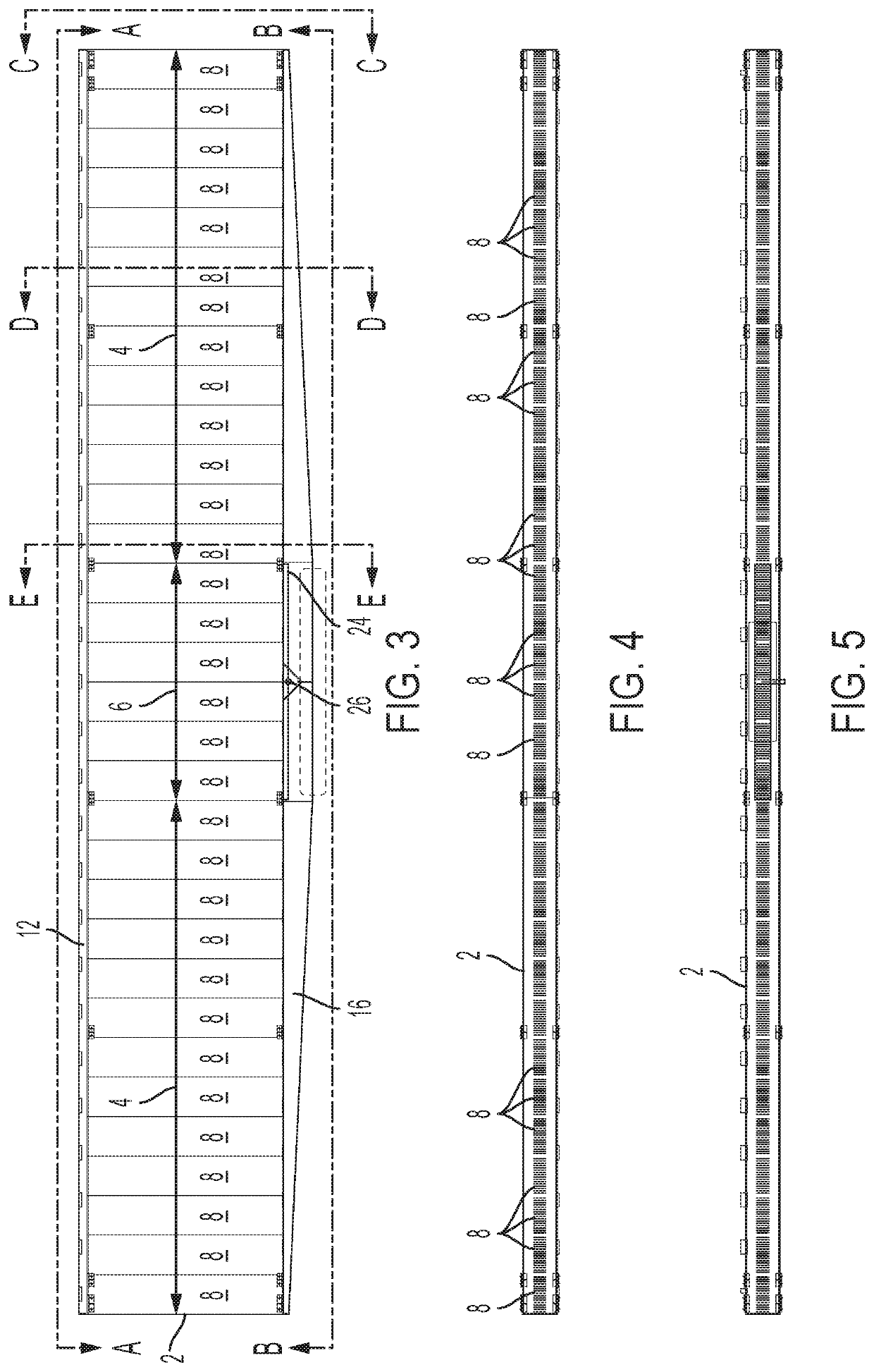
[0092]Referring FIGS. 3-8, the heat exchanger panel 2 according to a first embodiment of the present invention includes two primary condenser sections 4 flanking an integrated and centrally located secondary condenser section6. Each heat exchanger panel 2 consists of a plurality of separate condenser bundles 8, with a first subset of condenser bundles 8 making up the centrally located secondary section 6, and a second subset of different condenser bundles 8 making up each flanking primary section 4. The dimensions and constructions of the tubes 7 of the primary and secondary sections are preferably identical. At their top, all of the tubes 7 of both the primary and secondary sections 4, 6 are joined to a top tube sheet 10, on which sits a hollow top bonnet 12 which runs the length of the top of the heat exchanger panel 2. The bottom of all of the tubes 7 of the primary and secondary sections 4, 6 are connected to a bottom tube sheet 14, which forms the top of a bottom bonnet 16. The...


PUM


Abstract

A large scale field erected air cooled industrial steam condenser having heat exchanger panels independently loaded into and supported in a heat exchange frame section. A bottom bonnet runs along the bottom length of each heat exchanger panel for delivering steam to the bottom end of condenser tubes in the heat exchange panel and for receiving condensate formed in those same tubes. The tops of the tubes are connected to a top bonnet. Uncondensed steam and non-condensables are drawn into the top bonnet from the condenser tubes. A steam distribution manifold is suspended from the heat exchange section frame perpendicular to the longitudinal axis of the heat exchange panels and beneath a center point of the heat exchange panels and delivers steam to each heat exchange panel via a single steam inlet located at a center point of each bottom bonnet.

Description

CROSS REFERENCE TO RELATED APPLICATION[0001]This application is a continuation in part of U.S. patent application Ser. No. 16 / 562,778 entitled “ADVANCED LARGE SCALE FIELD-ERECTED AIR COOLED INDUSTRIAL STEAM CONDENSER,” filed with the U.S. Patent and Trademark Office on Sep. 6, 2019, which is based upon co-owned U.S. Provisional Patent Application Ser. No. 62 / 730,764 entitled “ADVANCED LARGE SCALE FIELD-ERECTED AIR COOLED INDUSTRIAL STEAM CONDENSER,” filed with the U.S. Patent and Trademark Office on Sep. 13, 2018, and U.S. Provisional Patent Application Ser. No. 62 / 728,269 entitled “ADVANCED LARGE SCALE FIELD-ERECTED AIR COOLED INDUSTRIAL STEAM CONDENSER,” filed with the U.S. Patent and Trademark Office on Sep. 7, 2018, the specification of which is incorporated herein by reference. This application also claims priority to U.S. Provisional Patent Application Ser. No. 62 / 900,195 entitled “ADVANCED LARGE SCALE FIELD-ERECTED AIR COOLED INDUSTRIAL STEAM CONDENSER,” filed with the U.S. P...

Claims


Application Information

Patent Timeline
Patent Type & Authority Patents(United States)
IPC IPC(8): F28B7/00F28B9/02F28B1/06
CPCF28B7/00F28B1/06F28B9/02F28D1/05366F28D1/0426
Inventor BUGLER, THOMAS W.LIBERT, JEAN-PIERREHUBER, MARKATHRON, TOBYSEXTON, WAYNEHILDEBRANDT, BEN
Owner EVAPCO
Why Eureka
Try Eureka