Advanced large scale field-erected air cooled industrial steam condenser

a technology of air-cooled industrial steam and condenser, which is applied in the direction of steam/vapor condensers, lighting and heating apparatus, stationary conduit assemblies, etc., can solve the problems of not providing a means for removing non-condensable gases and saving expensive field welding labor, and achieves the effect of convenient manufacture and convenient availability

Active Publication Date: 2020-03-12
EVAPCO
View PDF3 Cites 2 Cited by
  • Summary
  • Abstract
  • Description
  • Claims
  • Application Information

AI Technical Summary

Benefits of technology

[0014]According to a further embodiment, the new ACC design of the present invention may be used with 120 mm by 5 mm to 7 mm tubes having “Arrowhead”-type fins arranged at 9.8 fins per inch. According to an even further embodiment, the new ACC design of the present invention may be used with 140 mm by 5 mm to 7 mm tubes having “Arrowhead”-type fins arranged at 9.8 fins per inch. While the 120 mm and 140 mm configurations do not produce quite the same increase in capacity as the 200 mm configuration, both the 120 mm and 140 mm configurations have reduced materials and weight compared to the 200 mm design.
[0016]According to yet another embodiment, the new ACC design of the present invention may be used with tubes having “louvered” fins, which perform approximately as well as offset fins, and are more readily available and easier to manufacture.

Problems solved by technology

The first stage configuration is thermally efficient; however, it does not provide a means for removing non-condensable gases.
Another part of the logic is to weld the top steam manifold duct to each of the bundles at the factory and ship them together, thus saving expensive field welding labor.

Method used


Image

  • Advanced large scale field-erected air cooled industrial steam condenser
  • Advanced large scale field-erected air cooled industrial steam condenser
  • Advanced large scale field-erected air cooled industrial steam condenser

Examples


Embodiment Construction

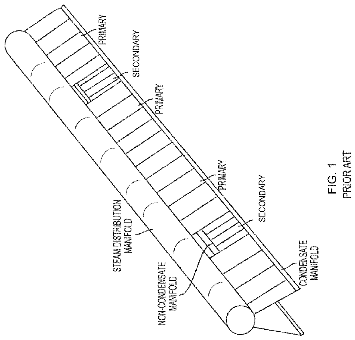
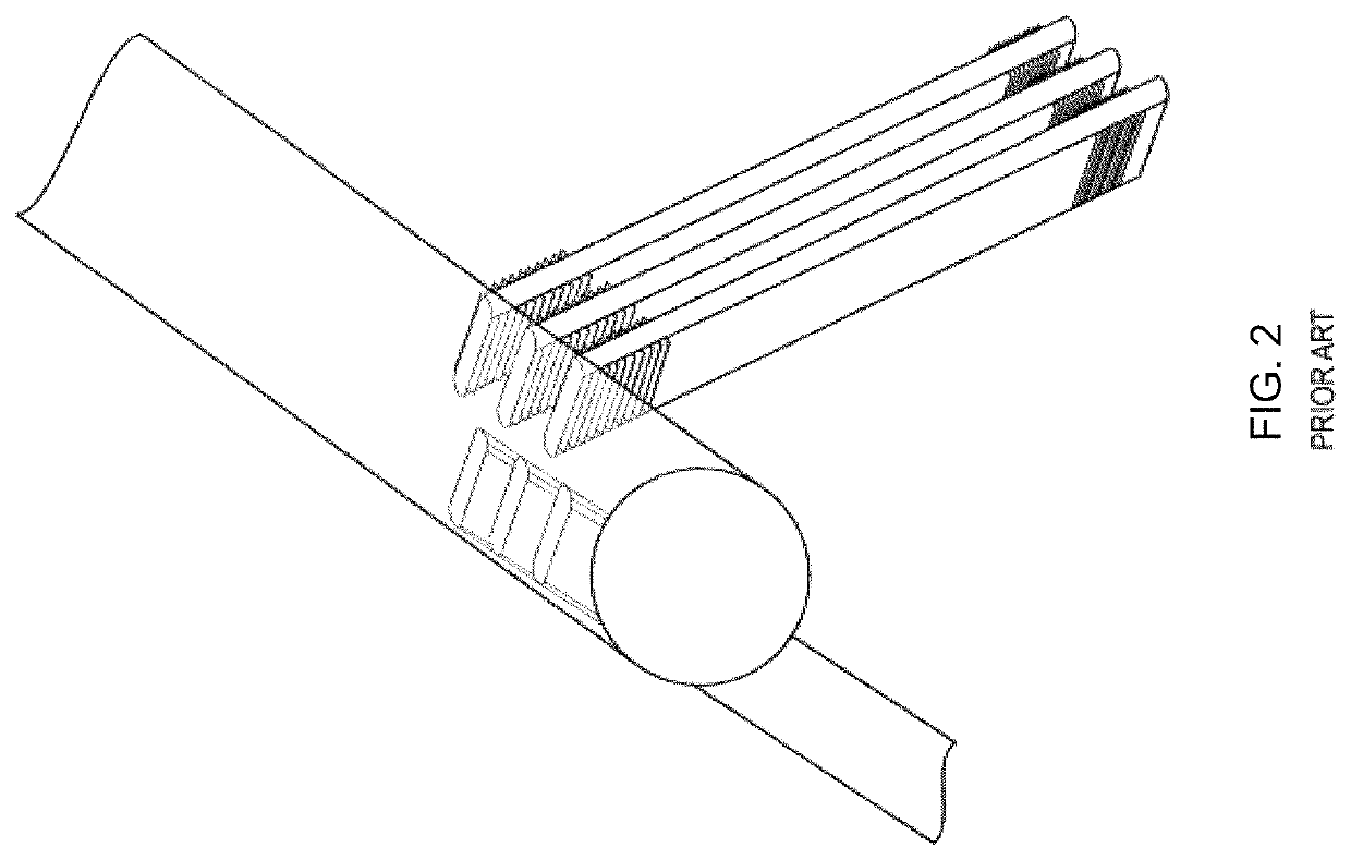
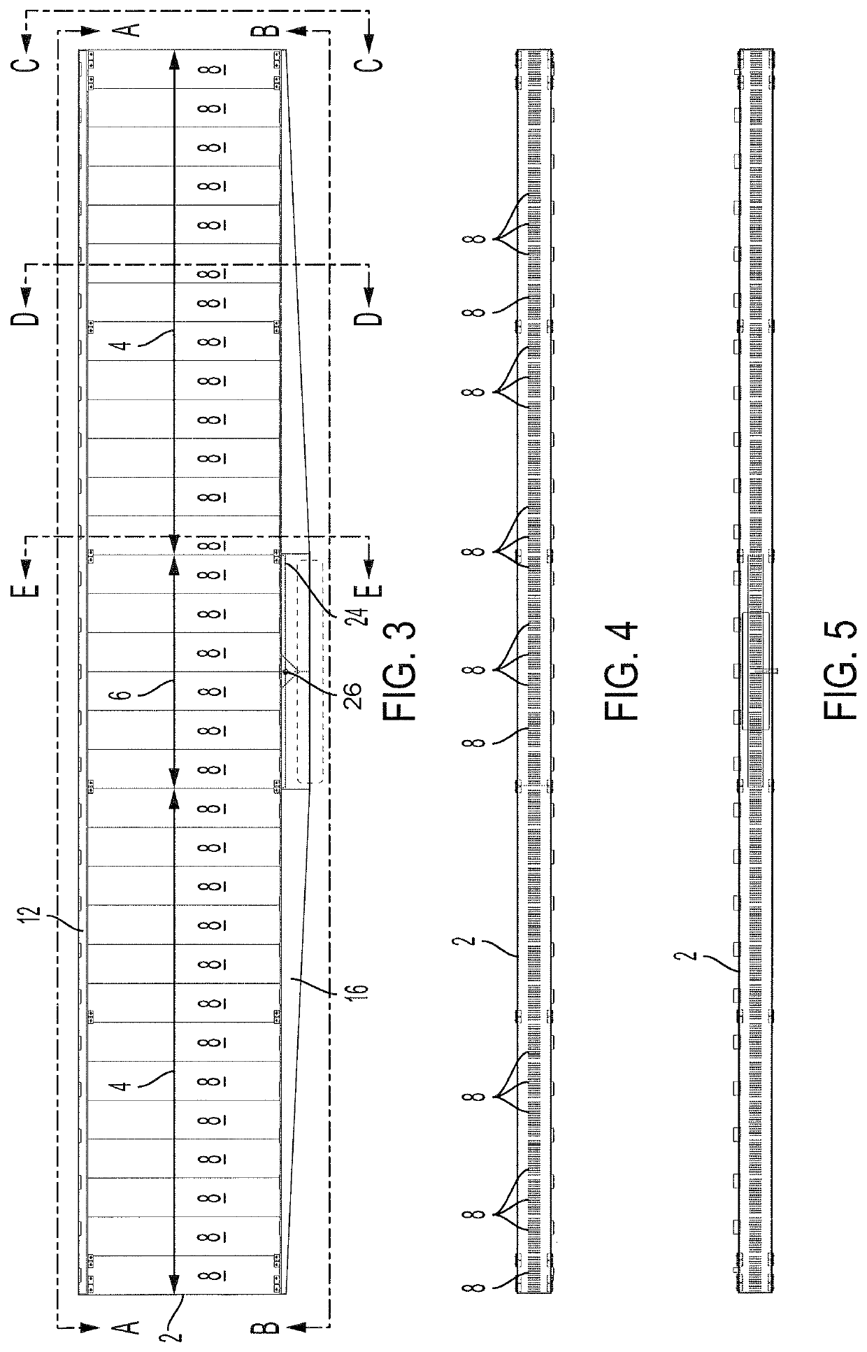
[0048]Referring FIGS. 3-8, the heat exchanger panel 2 of the present invention includes two primary condenser sections 4 flanking an integrated and centrally located secondary condenser section 6. Each heat exchanger panel 2 consists of a plurality of separate condenser bundles 8, with a first subset of condenser bundles 8 making up the centrally located secondary section 6, and a second subset of different condenser bundles 8 making up each flanking primary section 4. The dimensions and constructions of the tubes 7 of the primary and secondary sections are preferably identical. At their top, all of the tubes 7 of both the primary and secondary sections 4, 6 are joined to a top tube sheet 10, on which sits a hollow top bonnet 12 which runs the length of the top of the heat exchanger panel 2. The bottom of all of the tubes 7 of the primary and secondary sections 4, 6 are connected to a bottom tube sheet 14, which forms the top of a bottom bonnet 16. The bottom bonnet 16 likewise runs...


PUM


Abstract

Large scale field erected air cooled industrial steam condenser having heat exchanger bundles constructed with an integral secondary section positioned in the center of the heat exchanger, flanked by identical primary condenser sections. A bottom bonnet runs along the bottom length of the heat exchanger bundle, connected to the bottom side of the bottom tube sheet, for delivering steam to the bottom end of the primary condenser tubes and for receiving condensate formed in those same tubes. The tops of the tubes are connected to a top bonnet. Uncondensed steam and non-condensables flow into the top bonnet from the primary condenser tubes and flow toward the center of the heat exchanger bundle where they enter the top of the secondary condenser section tubes. Non-condensables and condensate formed in the secondary section tubes enter a secondary bottom bonnet inside the primary bottom bonnet and are withdrawn from the secondary bottom bonnet via outlet nozzle. Each cell of the ACC is fed by a single riser which delivers its steam to an upper steam distribution manifold suspended from and directly below the bundle support framework.

Description

BACKGROUND OF THE INVENTIONField of the Invention[0001]The present invention relates to large scale field erected air cooled industrial steam condensers.Description of the Background[0002]The typical large scale field erected air cooled industrial steam condenser is constructed of heat exchange bundles arranged in an A-frame arrangement above a large fan, with one A-frame per fan. Each tube bundle typically contains 35-45 vertically oriented flattened finned tubes, each tube approximately 11 meters in length by 200 mm in height, with semi-circular leading and trailing edges, and 18-22 mm external width. Each A-frame typically contains five to seven tube bundles per side.[0003]The typical A-Frame ACC described above also includes both 1st stage or “primary” condenser bundles (sometimes referred to as K-bundles for Kondensor) and 2nd stage or “secondary” condenser bundles (sometimes referred to as D-bundles for Dephlegmator). About 80% to 90% of the heat exchanger bundles are 1st stag...

Claims


Application Information

Patent Timeline
Patent Type & Authority Applications(United States)
IPC IPC(8): F28B1/06F28B9/02
CPCF28B1/06F28B9/02F28B2001/065F28B9/08F28D1/05366F28F9/002
Inventor BUGLER, THOMAS W.LIBERT, JEAN-PIERREHUBER, MARK
Owner EVAPCO
Why Eureka
Try Eureka