Foldable hay rake

a hay rake and foldable technology, applied in the field of foldable hay rakes, can solve the problems of cumbersome hay rakes, not always covering the field well, bending or damage to the lift tube, etc., and achieve the effect of reducing the wobbling of the castor wheel

Active Publication Date: 2009-06-02
ROWSE HYDRAULIC RAKES
View PDF21 Cites 19 Cited by
  • Summary
  • Abstract
  • Description
  • Claims
  • Application Information

AI Technical Summary

Benefits of technology

[0014]A foldable hay rake has two rake arms comprised of first and second rake arm structures with rake wheels thereon pivotally secured to a base frame to pivot in a vertical plane. A center rake arm structure is pivotally associated with the base frame with a center rake arm frame located adjacent a rearward end of the base frame between the first and second rake arm structures. At least one of the hay rake wheels has a plurality of teeth extending therefrom with a tooth spacing between adjacent teeth of less than five inches and an outer diameter greater than 60 inches. A castor wheel is pivotally attached to the outer end of the main support frame, with an axle dampener operationally associated with the castor wheel to dampen wobbling of the castor wheel.

Problems solved by technology

Among them are that the rakes are cumbersome to use both in operation and for travel; they require substantial room for turning and maneuvering; they do not adapt well to uneven ground; they are susceptible to damage in the field, and they do not always cover the field well to deal with all the hay that is being raked.
The problem with existing foldable hay rakes is that pushing from the rearward end of the lift tube to raise the individual raking wheels often bends or damages the lift tube.
Also, with larger diameter rake wheels exceeding 60 inches in outside diameter, the teeth are spaced greater than four inches apart which causes problems raking fine hay and leads to a loss in yield.
Another problem with existing foldable hay rakes is that they leave a path in the center of the raking machine where hay is turned in for bailing that remains unraked.
This unraked portion that lies underneath the turned in portion is more difficult to pick up during harvesting or baling leading to lost yields and reduced growth in future harvests.

Method used


Image

  • Foldable hay rake
  • Foldable hay rake
  • Foldable hay rake

Examples


Embodiment Construction

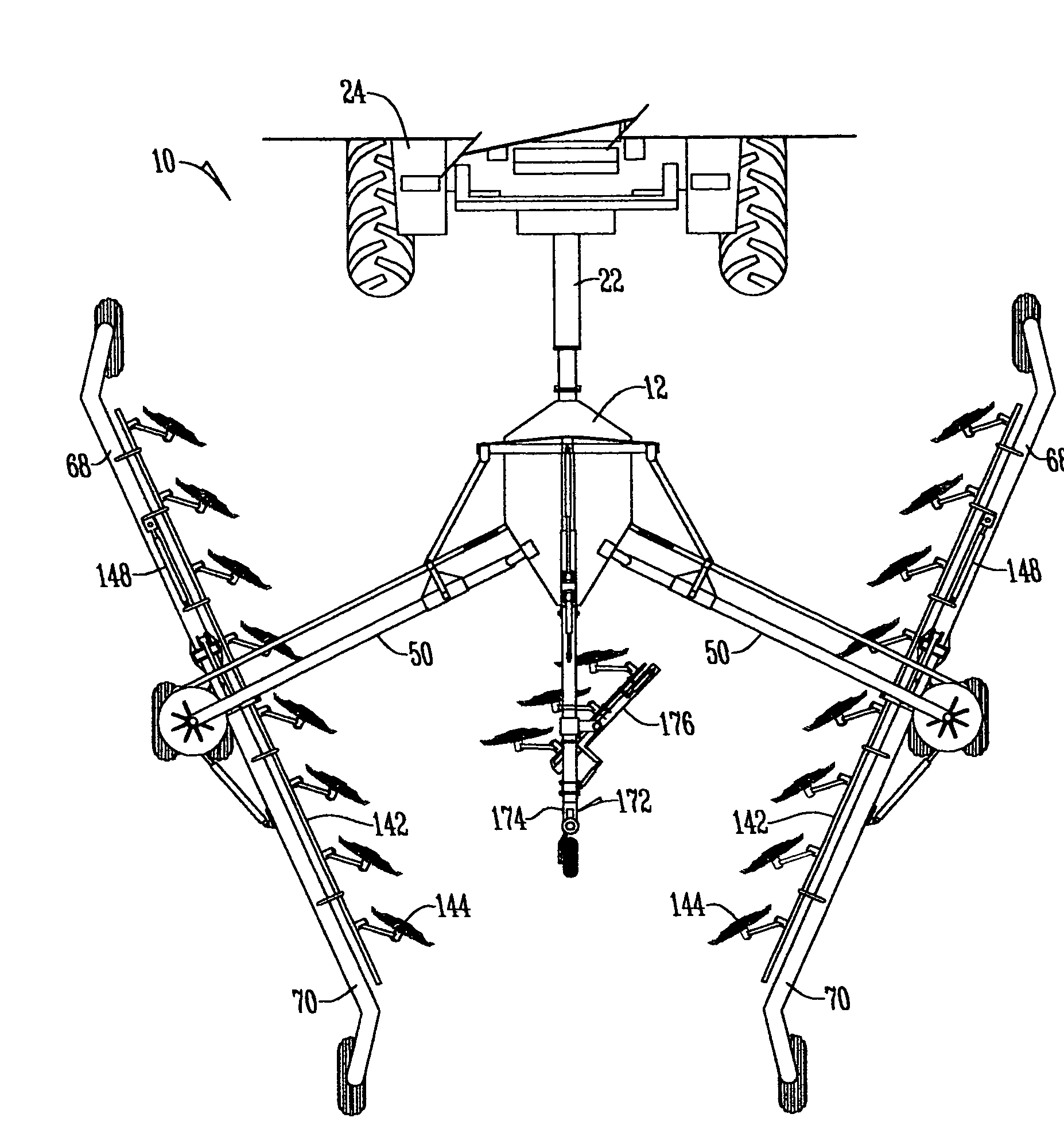
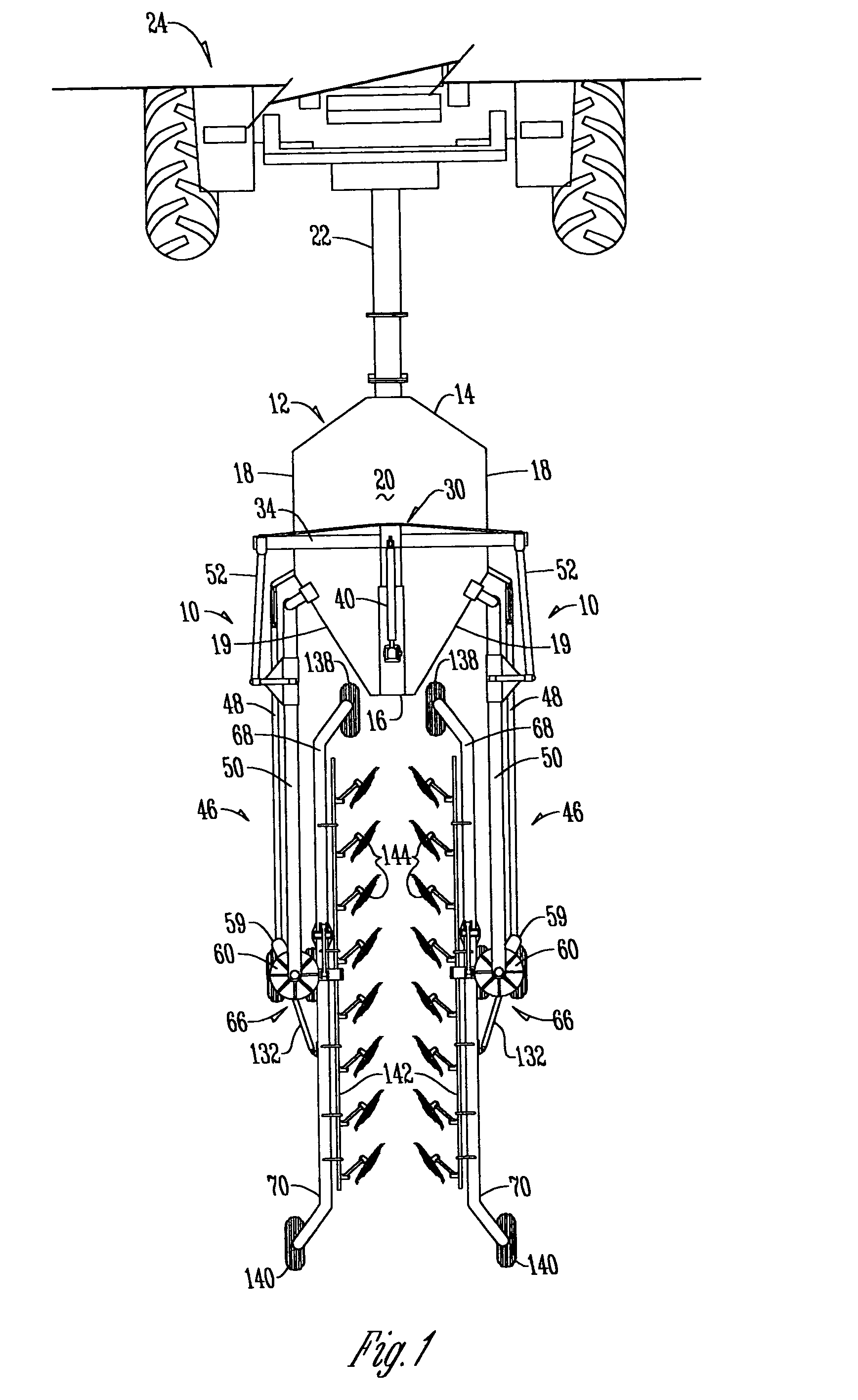
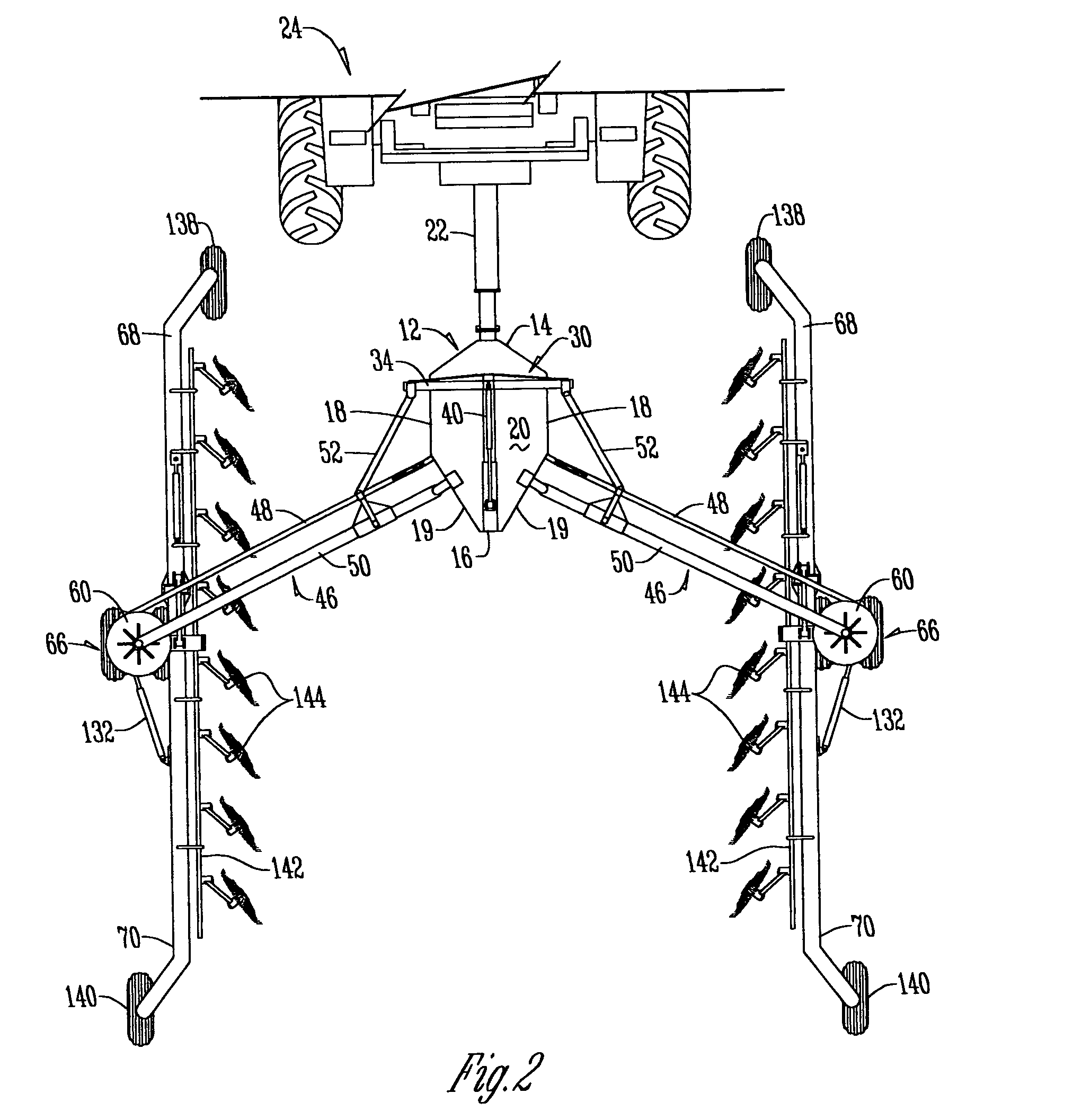
[0046]The hay rake 10 has a base frame 12 which is normally in a substantially horizontal position. (FIG. 5). Base frame 12 has a forward end 14, a rearward end 16, parallel sides 18, diagonal sides 19, an upper flat deck 20, and a bottom plate 21 (FIGS. 17, 18). A tongue 22 is rigidly secured to the forward end 14 and extends downwardly and forwardly to be connected to the drawbar of a conventional farm tractor 24.

[0047]With reference to FIGS. 5-8, a hollow guide housing 26 is rigidly secured to and extends from the rearward end of base frame 12 in a forward direction along the centerline of the base frame and terminates at an open forward end 28. A T-beam 30 comprised of a forwardly extending beam 32 is slidably mounted in housing 26 with its forward end terminating in a transverse forward beam 34 with outer ends 36. The beam 32 is covered with a layer of vinyl plastic 38 or the like to enhance the sliding movement of beam 32 in housing 26 without the need for lubrication.

[0048]A ...


PUM


Abstract

A foldable hay rake has two rake arms comprised of first and second rake arm structures with rake wheels thereon pivotally secured to a base frame to pivot in a vertical plane. A center rake arm structure is pivotally associated with the base frame with a center rake arm frame located adjacent a rearward end of the base frame between the first and second rake arm structures. At least one of the hay rake wheels has a plurality of teeth extending therefrom with a tooth spacing between adjacent teeth of less than five inches and an outer diameter greater than 60 inches. A castor wheel is pivotally attached to the outer end of the main support frame, with an axle dampener operationally associated with the castor wheel to dampen wobbling of the castor wheel.

Description

CROSS REFERENCE TO RELATED APPLICATION[0001]This application claims the benefit of U.S. Provisional Application No. 60 / 602,031, filed Aug. 16, 2004.FIELD OF THE INVENTION[0002]This invention relates to large foldable hay rakes that can move through a hay field of cut hay in a swath up to 40 feet wide or greater to turn the hay and present the hay in elongated windrows ready for harvesting or baling, usually in large round or square bales weighing almost a ton or more.BACKGROUND OF THE INVENTION[0003]This invention is an improvement over prior and existing large foldable hay rakes such as that shown in U.S. Pat. No. 5,899,055.[0004]Existing foldable hay rakes typically have a pair of wheel supported elongated rake arms that are pivotal along their lengths, and capable of being pivoted individually with respect to each other. While substantially advancing the art of hay raking, these devices have certain shortcomings. Among them are that the rakes are cumbersome to use both in operati...

Claims


Application Information

Patent Timeline
Patent Type & Authority Patents(United States)
IPC IPC(8): A01D76/00
CPCA01D78/146
Inventor ROWSE, DAN DROWSE, RODNEY D
Owner ROWSE HYDRAULIC RAKES
Why Eureka
Try Eureka