
Impact resistant battery housing with cover

a battery and cover technology, applied in the field of impact-resistant battery housings, can solve the problems of high impact load during product testing, battery shifting at least partially out of alignment, and failure of the device intended to be powered by the battery, such as the transmitter, to achieve the effect of minimizing the mis-alignment of the battery

Inactive Publication Date: 2009-07-07
HONEYWELL INT INC
View PDF2 Cites 5 Cited by
  • Summary
  • Abstract
  • Description
  • Claims
  • Application Information

AI Technical Summary

Benefits of technology

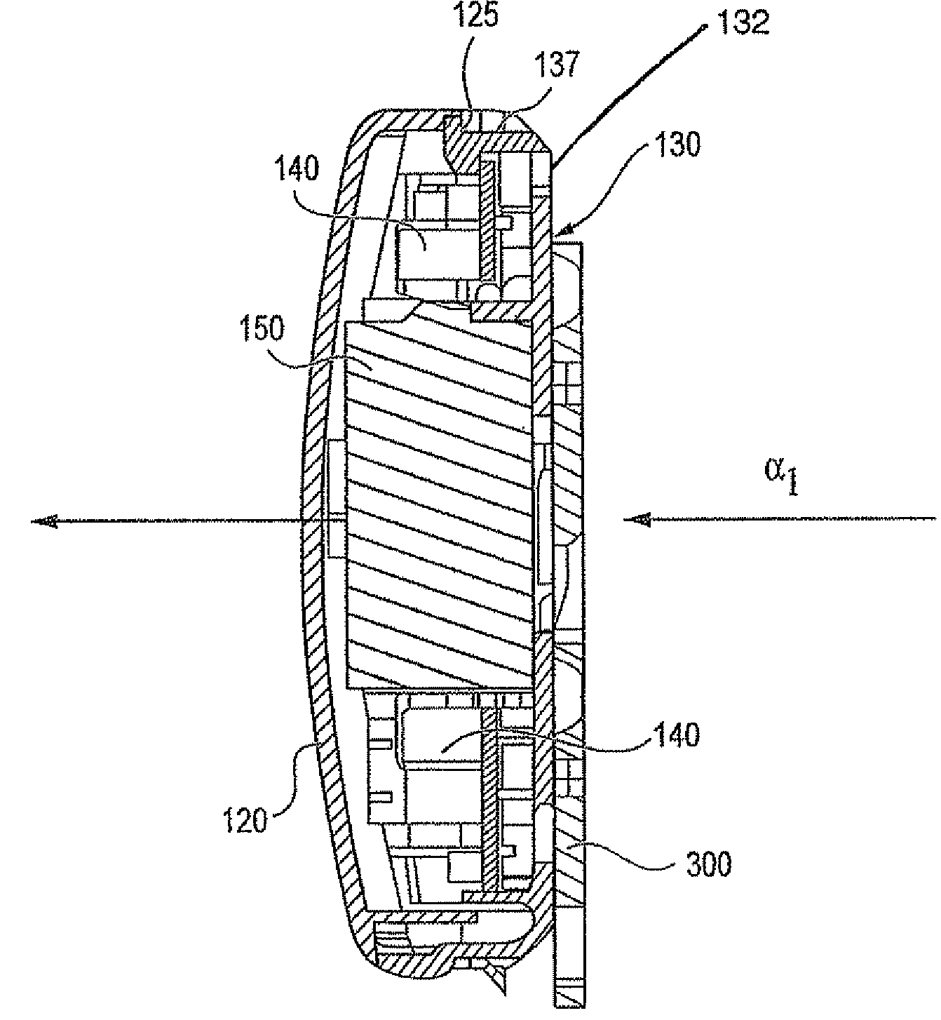
The invention provides a battery housing unit that minimizes mis-alignment of the battery even when high impact loads are delivered to the housing unit. The battery holder is comprised of a base and flexible retention members that secure the battery in place. The cover of the housing unit is designed to fit over the battery holder and base and includes stop ribs that engage with detents on the retention members to further secure the battery. The battery holder and cover are made of lightweight materials that make replacement or access to the battery easy. The technical effect of the invention is to provide a battery housing unit that can withstand high impact loads and maintain the battery's alignment.

Problems solved by technology

Such high impact loads may occur during product testing, such as UL 636 jarring tests, or in the case of door or window mounted transmitters, for example, during the slamming of the door the transmitter is mounted upon.
Often such high impact loads cause a battery to shift at least partially out of alignment with the contacts of the device that is to be powered by the battery.
As a result, failure of the device intended to be powered by the battery, such as a transmitter, may occur.
While aiding retention of the battery in a desired position, such covers often render replacement of a battery more difficult due to the heavier materials, additional structures or screws used to comprise the cover and housing unit.

Method used


Image

  • Impact resistant battery housing with cover
  • Impact resistant battery housing with cover
  • Impact resistant battery housing with cover

Examples


Embodiment Construction

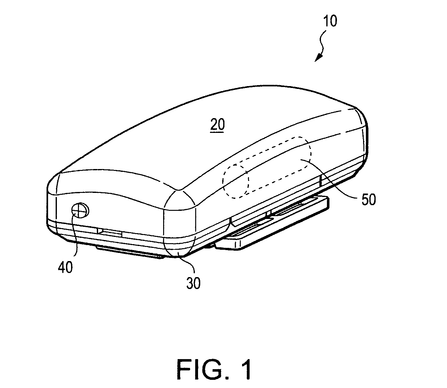
[0025]FIG. 1 illustrates an exemplary prior art battery housing unit 10 whereby a cover 20 is secured to a base 30 by screws 40 penetrating through corners of the cover 20 and into the base 30. A battery 50 (shown in dashed lines) is housed between the base 30 and cover 20. The screws 40 retain the cover 20 in fitting relation with the base 30 so that the battery is maintained therebetween even during high impact loads. In the absence of the screws, the cover 20 would likely separate from the base 30 upon delivery of a high impact load to the housing unit.

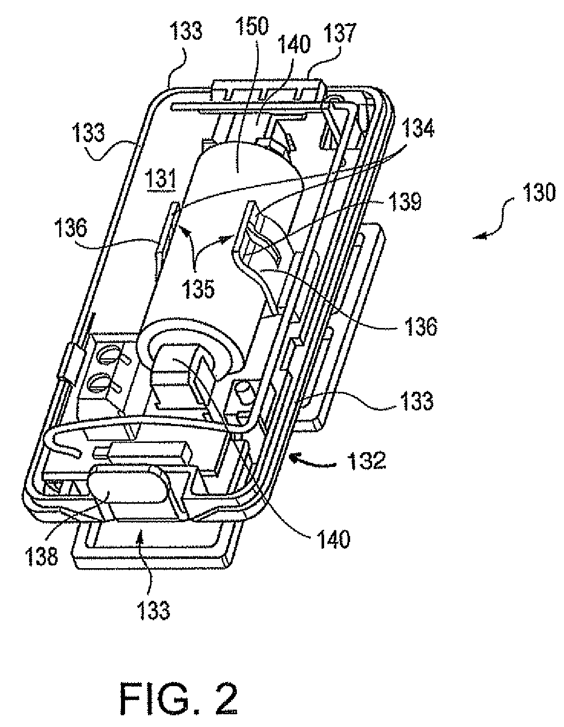
[0026]FIG. 2 illustrates a base 130 of a housing unit according to one exemplary embodiment of the invention. As shown in FIG. 2, the base 130 comprises an interior surface 131, an exterior surface 132 (not shown) opposite the interior surface 131, and a plurality of sides 133 connecting the interior and exterior surfaces. At least one pair of flexible retention members 134 project from the interior surface 131 of the base 130 and ...


PUM

PropertyMeasurementUnit
flexibleaaaaaaaaaa
lengthaaaaaaaaaa
sizeaaaaaaaaaa

Abstract

A battery housing unit with a releasable cover for minimizing mis-alignment of a battery housed therein during high impact loads. The battery unit includes a battery holder having retention members biased towards one another that receive a battery. The retention members engage stop ribs projecting from the cover. The cover fits over the retention members of the battery holder and to a base of the housing unit. The retention members and stop ribs are engaged when high impact loads are delivered to the housing unit and the battery is urged against the biasing nature of the retention members. Movement and mis-alignment of the battery is thus minimized and high impact loads are re-distributed throughout the cover. Detents may be provided on each retention member for engaging a corresponding cavity provided on each stop rib. The detents and cavities interlock the retention members and stop ribs together upon high impact. In this manner, movement and mis-alignment of the battery is also minimized.

Description

BACKGROUND OF THE INVENTION[0001]1. Field of the Invention[0002]The invention generally relates to systems and methods for providing an impact resistant battery housing. More specifically, the invention relates to systems and methods for providing an impact resistant battery housing with a lightweight cover that helps maintain a battery in a desired position within the battery housing while minimizing the effects of high impact loads delivered to the housing.[0003]2. Related Art[0004]Battery housing units for retaining a battery in place are widely known. Ideally, the housing units retain the battery in a position whereby leads at ends of the battery are aligned with contacts provided on a device to be powered by the battery. Preferably, this alignment of the battery is maintained even when the device or housing unit is subjected to high impact loads. Such high impact loads may occur during product testing, such as UL 636 jarring tests, or in the case of door or window mounted trans...

Claims


Application Information

Patent Timeline
Patent Type & Authority Patents(United States)
IPC IPC(8): H01M2/10H01M50/202H01M50/213H01M50/227H01M50/262H01M50/271
CPCH01M2/1022H01M2/1055Y02E60/10H01M50/213H01M50/202H01M50/227H01M50/271H01M50/262
Inventor HSU
Owner HONEYWELL INT INC
Learn More