Planar display structure with LED light source

Inactive Publication Date: 2009-07-07
INNOLUX CORP
View PDF11 Cites 45 Cited by
  • Summary
  • Abstract
  • Description
  • Claims
  • Application Information

AI Technical Summary

Benefits of technology

[0010]In the light of the state of the art described above, it is an object of the present invention to provide a light guide plate with a plurality of recesses that the LEDs can be put into which is immune to the problems of the conventional

Problems solved by technology

It has a main disadvantage that the light rays emitted from plane light source are not well distributed, in other words, the illumination of the portion of wedge light guide plate near the light source is higher than the other portion.
Besides, the unsteady matter of CCFL that shortens the lift cycle of device is a dr

Method used


Image

  • Planar display structure with LED light source
  • Planar display structure with LED light source
  • Planar display structure with LED light source

Examples


Example

[0046]Some sample embodiments of the present invention will now be described in greater detail. Nevertheless, it should be recognized that the present invention can be practiced in a wide range of other embodiments besides those explicitly described, and the scope of the present invention is expressly not limited except as specified in the accompanying claims.

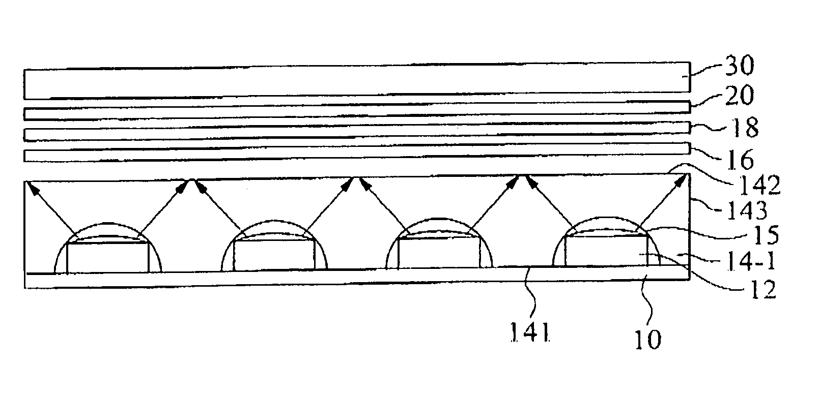
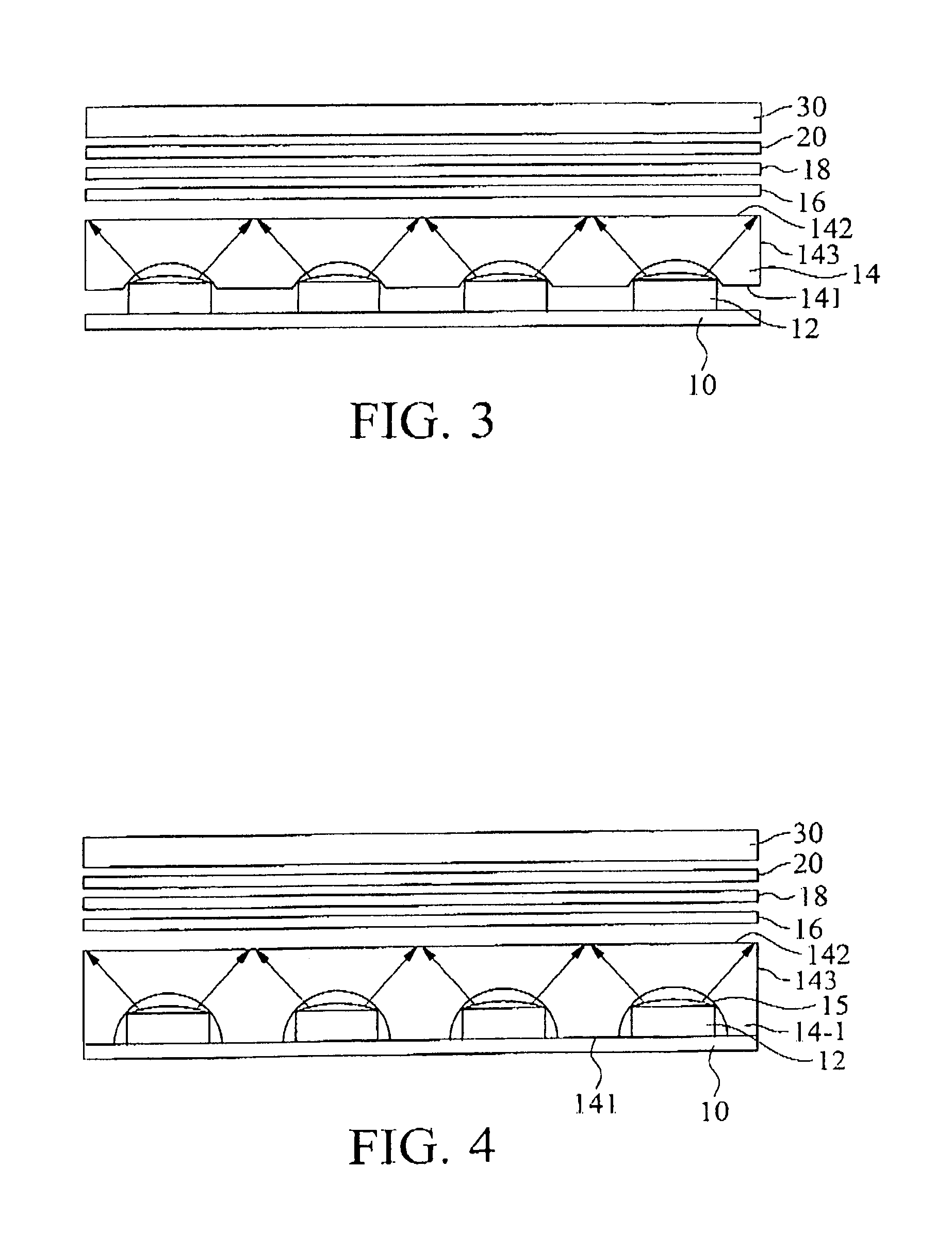
[0047]Next, a planar display structure with LED light source is illustrated according to this invention. Please refer to FIG. 3, a plane light source is constituted by a plurality of LEDs 12 on a substrate 10. The substrate 10 can be printed circuit board (PCB) or flexible printed circuit board (FPC). The LEDs 12 are welded on the substrate 10 and electrically connected to power supply by the circuit on the substrate 10. A light guide plate 14 is placed above the substrate 10 and the LEDs 12, and the upper edge surface of light guide plate 14 is a light-emitting surface 142. The lower edge surface of the light guide plate 14 is...


PUM


Abstract

A planar display structure with LED light source includes a plane light source constituted by a plurality of LEDs and a light guide plate, wherein the light guide plate has a plurality of recesses that the above LEDs can be put into.

Description

BACKGROUND OF THE INVENTION[0001]1. Field of the Invention[0002]The present invention generally relates to a planar display structure, and more particularly to a planar display structure with LED (light emitting diode) light source.[0003]2. Description of the Prior Art[0004]Presently many display devices need to use plane light sources, such as transmissive-type / reflective-type liquid crystal display (LCD) or scanner so that the development of plane light source art is fast and attentive. The light source mainly used by LCD device is constituted by line light source formed with LED or cold cathode fluorescent lamp (CCFL). The light rays emitted from the light source at a lateral end of wedge light guide plate are guided almost vertically into the panel by the wedge light plate. The above structure is referred to U.S. Pat. No. 6,309,080, surface light source device and liquid crystal display. It has a main disadvantage that the light rays emitted from plane light source are not well ...

Claims


Application Information

Patent Timeline
IPC IPC(8): G09G3/30F21V8/00G02F1/13357G09G3/32
CPCG02B6/0021G02F1/133603G02B6/0068G02B6/0073
Inventor CHUANG, MENG JUMAI, CHE-KUEI
Owner INNOLUX CORP
Why Eureka
Try Eureka