
Air-cooled thermal management for a fuel cell stack

Active Publication Date: 2012-05-01
HYAXIOM INC
View PDF10 Cites 3 Cited by
  • Summary
  • Abstract
  • Description
  • Claims
  • Application Information

AI Technical Summary

Benefits of technology

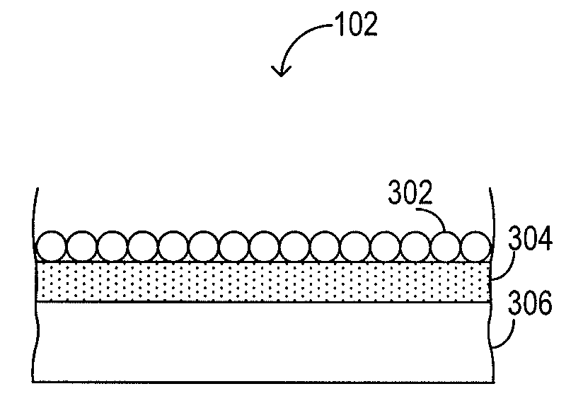
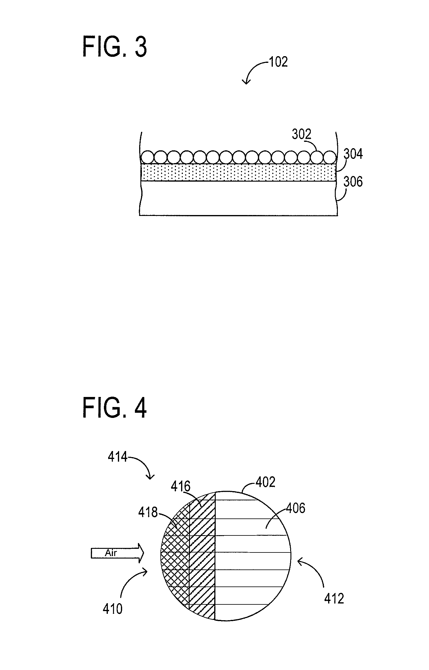
[0003]Various embodiments related to the air-cooled thermal management of a fuel cell stack are disclosed herein. For example, one disclosed embodiment comprises a cooling plate apparatus for an air-cooled fuel cell stack. The cooling plate comprises a body configured to receive heat from one or more fuel cells in thermal communication with the body. The cooling plate further comprises one or more airflow channels formed in the body and configured to allow a flow of a cooling air to pass across the body. Further, an insulating structure is disposed in the airflow channels, wherein

Problems solved by technology

In such a fuel cell, operating the fuel cell at too high of temperatures may damage the fuel cell system, while operating the fuel cell at too low of temperatures may limit cell performance and cause irrecoverable damage.

Method used


Image

  • Air-cooled thermal management for a fuel cell stack
  • Air-cooled thermal management for a fuel cell stack
  • Air-cooled thermal management for a fuel cell stack

Examples


Embodiment Construction

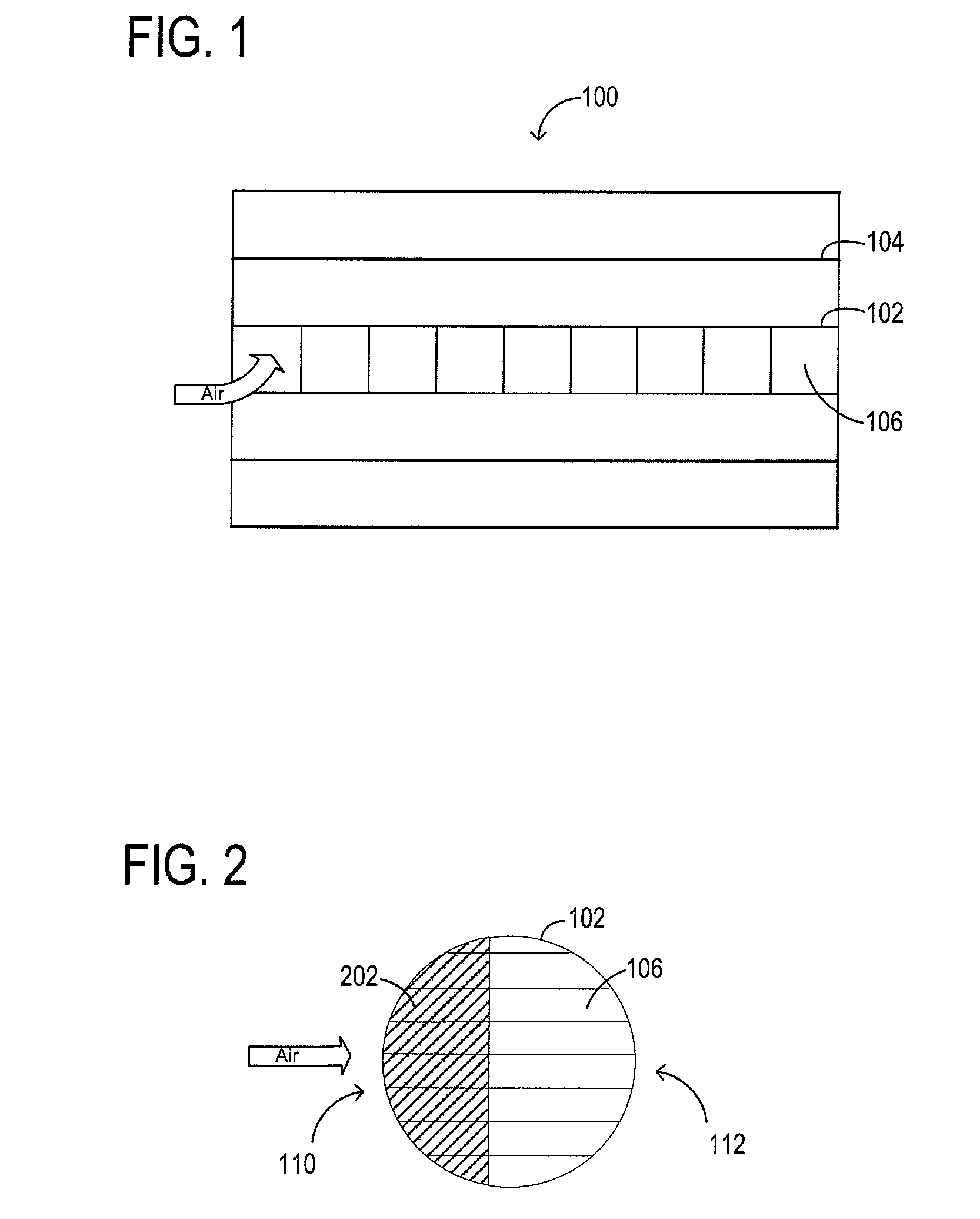
[0011]FIG. 1 shows a schematic depiction of an embodiment of a fuel cell system 100. Fuel cell system 100 comprises a cooling plate 102 positioned between a plurality of fuel cells 104 such that cooling plate 102 conducts heat away from the fuel cells 104. In one embodiment, fuel cells 104 are high-temperature PEM fuel cells. Details of fuel cell system 100, such as electrodes, electrolytes, and electrical components are not shown for the purpose of clarity.

[0012]Continuing with FIG. 1, cooling plate 102 comprises a plurality of airflow channels 106 configured to allow a flow of a cooling air across cooling plate 102 to thereby remove heat from the cooling plate. In this manner, cooling plate 102 may help to maintain the fuel cell system 100 within a desired temperature range, and therefore facilitate longevity and proper operation of the fuel cell.

[0013]Due to the nature of heat transfer between air and metal, the cooling air may initially increase in temperature relatively rapidly...


PUM

PropertyMeasurementUnit
Temperatureaaaaaaaaaa
Thicknessaaaaaaaaaa
Flow rateaaaaaaaaaa

Abstract

The air-cooled thermal management of a fuel cell stack is disclosed. One disclosed embodiment comprises a cooling plate apparatus for an air-cooled fuel cell stack, where the cooling plate comprises a body configured to receive heat from one or more fuel cells in thermal communication with the body, and airflow channels formed in the body and configured to allow a flow of a cooling air to pass across the body. An insulating structure is disposed in the airflow channels, wherein the insulating structure has decreasing thickness from a cooling air inlet toward a cooling air outlet.

Description

BACKGROUND[0001]A high-temperature proton exchange membrane (PEM) fuel cell system may be air-cooled. Such a fuel cell system may comprise a stack of fuel cells with cooling plates interspersed within the stack. The cooling plates each may comprise airflow channels through which a cooling air passes to cool the fuel cells. Heat from the fuel cell stack is conducted to cooling plates, and removed from the plates by air flowing through the airflow channels.[0002]One type of high-temperature PEM fuel cell utilizes an electrolyte membrane formed from polybenzimidazole (PBI) and phosphoric acid. Such fuel cells are often operated at temperatures within a range of 120° C. to 180° C., depending upon a specific fuel cell system design. In such a fuel cell, operating the fuel cell at too high of temperatures may damage the fuel cell system, while operating the fuel cell at too low of temperatures may limit cell performance and cause irrecoverable damage.SUMMARY[0003]Various embodiments relat...

Claims


Application Information

Patent Timeline
IPC IPC(8): H01M8/04
CPCB32B37/12H01M8/04029H01M8/04074H01M8/241H01M8/2465B32B2315/08B32B2457/18H01M2008/1095Y02E60/50H01M8/0267
Inventor HAWKINS, GEORGE W.KABIR, ZAKIULMING, QIMINSONG, YANG
Owner HYAXIOM INC
Learn More