Rear projection display device

Inactive Publication Date: 2008-01-31
SONY CORP
View PDF12 Cites 3 Cited by
  • Summary
  • Abstract
  • Description
  • Claims
  • Application Information

AI Technical Summary

Benefits of technology

[0013]With this configuration, a rear projection display device may be provided that realizes increase

Problems solved by technology

Unfortunately, the known rear projection display devices designed for realizing the reduction in thickness may cause some problems.
In particular, distortion may

Method used


Image

  • Rear projection display device
  • Rear projection display device
  • Rear projection display device

Examples


Example

First Embodiment

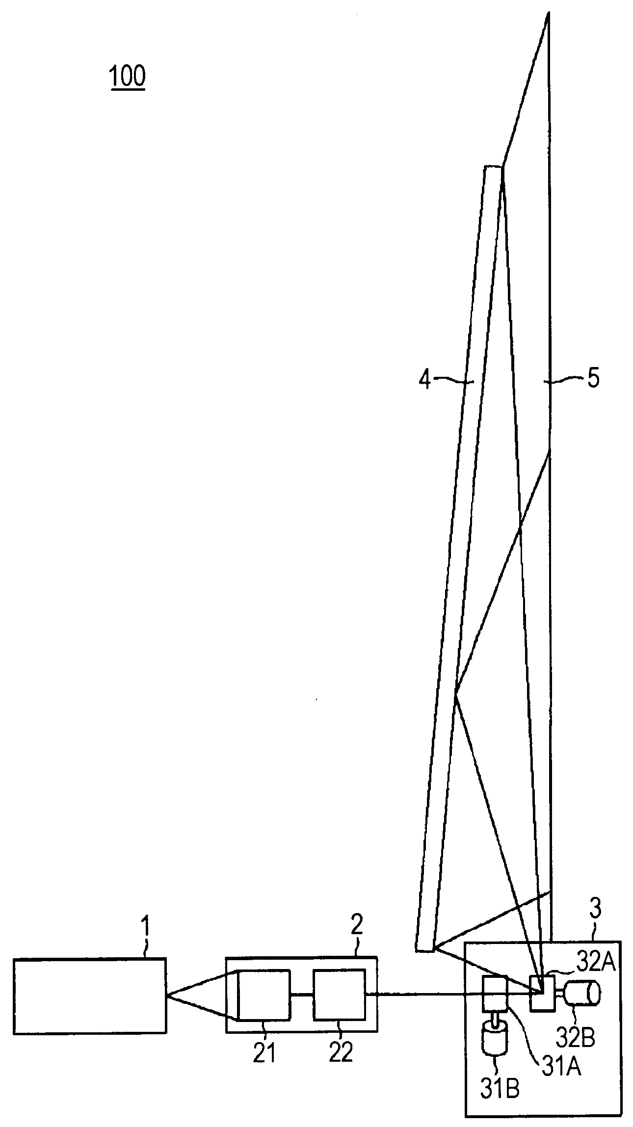
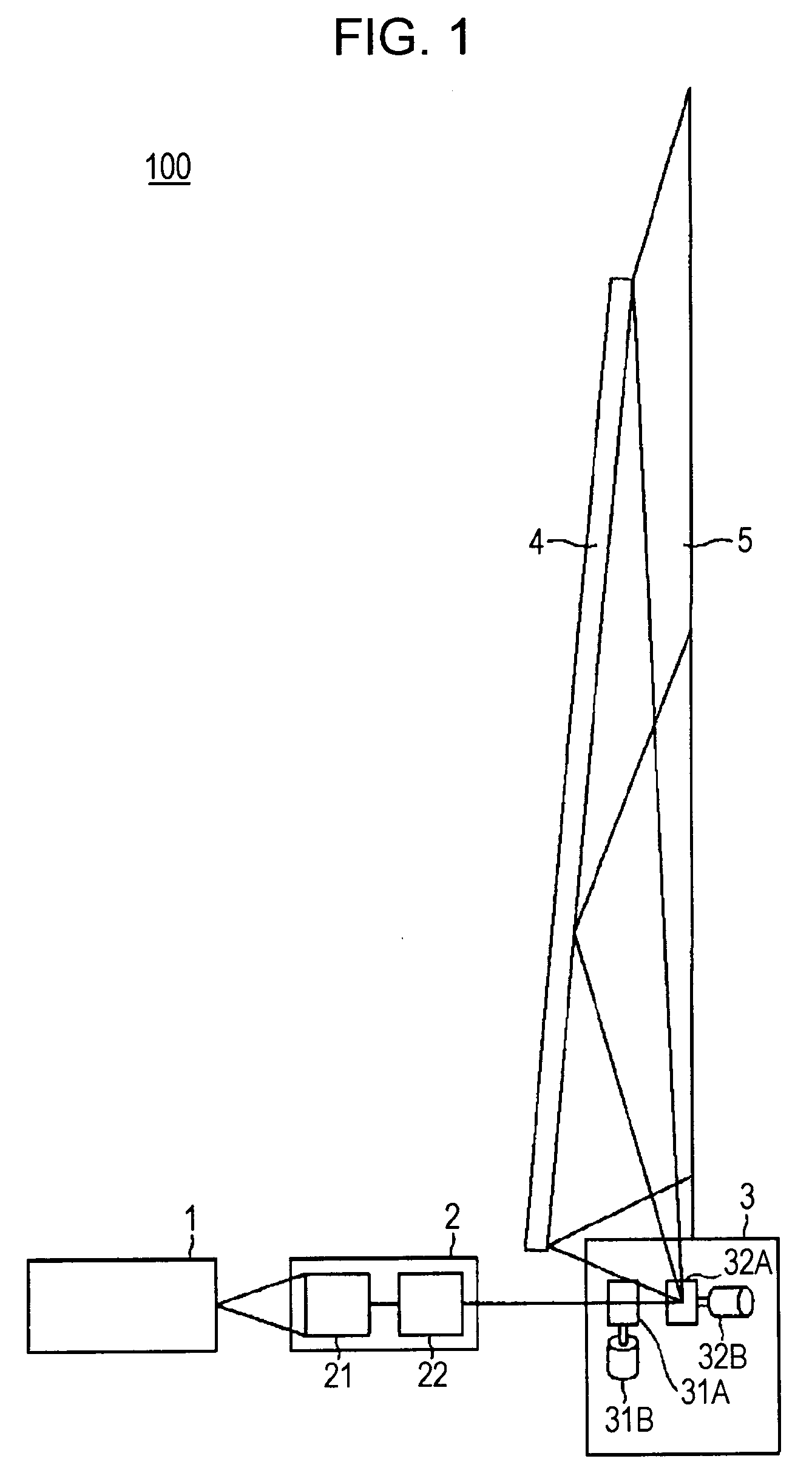
[0021]FIG. 1 is a schematic illustration showing an inner structure of a rear projection display device 100 according to a first embodiment to which the present invention is applied. The rear projection display device 100 includes a light source 1, an optical element 2, a scanning section 3, a light-guiding screen mirror 4, and a screen 5. The optical element 2 has a pencil-shaping optical element 21 and a pencil-conversion optical element 22.

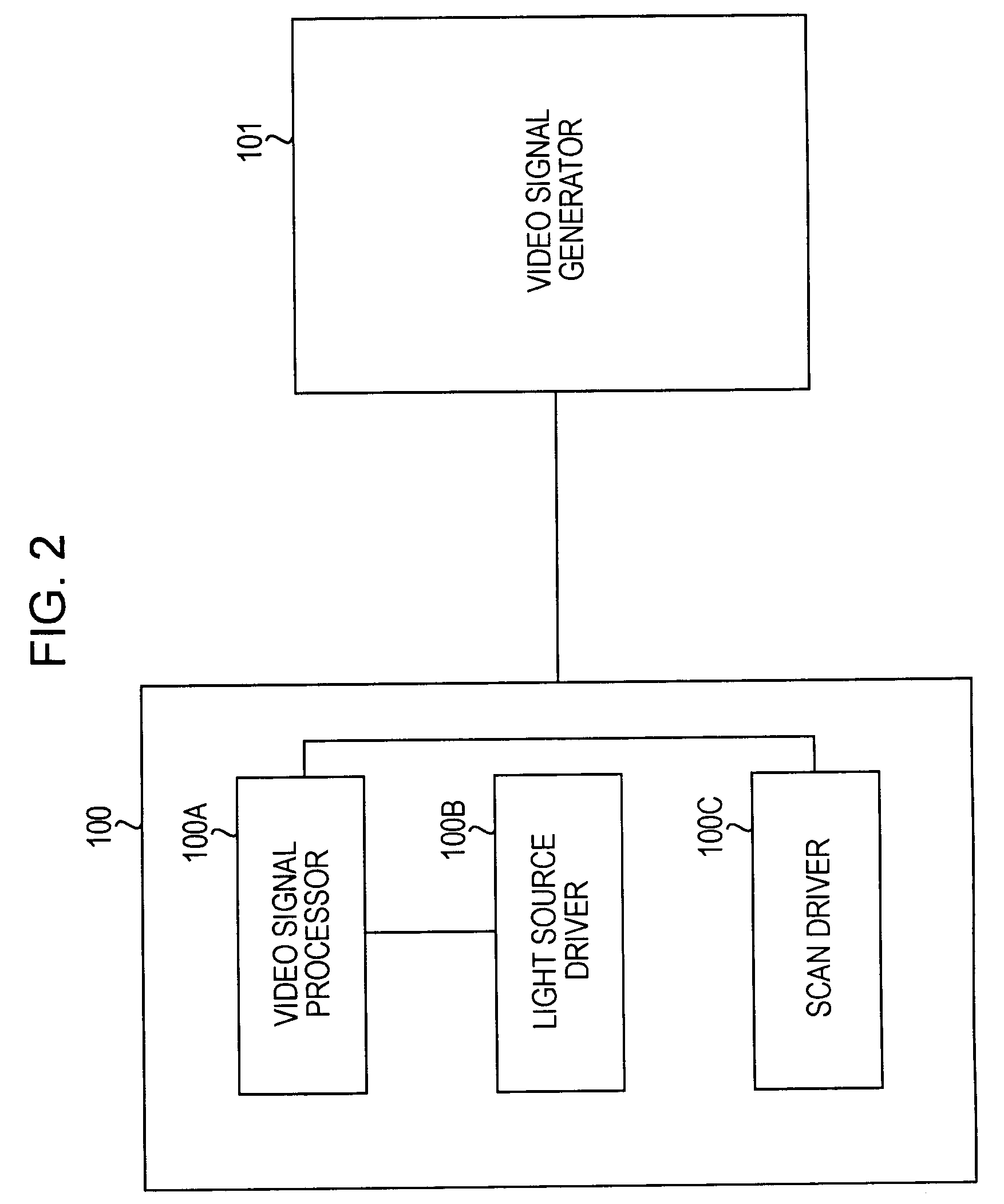
[0022]FIG. 2 is an illustration showing a system configuration of the rear projection display device 100. The rear projection display device 100 may receive various video signals when being connected to a video signal generator 101, such as a video player, a video camera, a video recorder, a broadcasting tuner, or the Internet. The rear projection display device 100 includes a video signal processor 100A that processes video signals input by the video signal generator 101, a light source driver 100B that drives the light source ...

Example

Second Embodiment

[0042]FIG. 5 is a schematic illustration showing an inner structure of a rear projection display device 200 according to a second embodiment to which the present invention is applied. Like numerals refer like components as in the above-described rear projection display device 100, and their detailed descriptions are omitted.

[0043]The rear projection display device 200 has a light-guiding screen mirror 40 which has a shape configured such that a curvature in the vertical direction is greater than a curvature in the horizontal direction, and has a concave toric surface with respect to the screen 5.

[0044]The correlation between the light-guiding screen mirror 4 and the screen 5 in view of their positions and sizes for the rear projection display device 200 is similar to that shown in FIG. 4B. As shown in FIG. 6, the shape of the light-guiding screen mirror 40 is determined such that the curvature in the vertical direction is greater than the curvature in the horizontal...


PUM


Abstract

A rear projection display device that projects an image on a rear side of a screen includes a light source, an optical element, a scanning unit, and a reflecting plate. The light source emits a light beam. The optical element converts the light beam emitted from the light source into a substantially collimated light beam. The scanning unit performs scanning with the substantially collimated light beam converted by the optical element so as to allow the substantially collimated light beam to be incident on the screen. The reflecting plate has a height which is at least ½ of a height of the screen. The reflecting plate reflects the light beam from the scanning unit so that the light beam is incident on the screen.

Description

CROSS REFERENCES TO RELATED APPLICATIONS[0001]The present invention contains subject matter related to Japanese Patent Application JP 2006-206731 filed in the Japanese Patent Office on Jul. 28, 2006, the entire contents of which are incorporated herein by reference.BACKGROUND OF THE INVENTION[0002]1. Field of the Invention[0003]The present invention relates to a rear projection display device that performs scanning with a light beam to project an image on a rear side of a screen from.[0004]2. Description of the Related Art[0005]Rear projection display devices are becoming popular as display devices following liquid crystal television devices and plasma television devices. The rear projection display devices are rapidly spread because they are markedly cheaper than rear projection plasma television devices.[0006]The system employed by the rear projection display devices is shifted from a known cathode ray tube (CRT) system to a system with a micro display, such as a liquid crystal di...

Claims


Application Information

Patent Timeline
IPC IPC(8): G03B21/28
CPCG03B21/28H04N9/3141H04N9/3129G03B21/62G02B17/0605G02B27/18
Inventor IWASAKI, MASANORI
Owner SONY CORP
Why Eureka
Try Eureka