Toilet seat

Inactive Publication Date: 2016-02-04
RANFT DONALD
13 Cites 3 Cited by

AI-Extracted Technical Summary

Problems solved by technology

For example, simply enlarging the entire toilet seat or supporting an individual's weight without supporting their skeletal structure is not biomedically desirable.
A particular problem arises in the cas...

Benefits of technology

[0010]In another embodiment, the invention is a toilet seat configured for supporting an overweight person seated atop a toilet having a bowl with an upper rim spaced between an inner and outer circumference. The seat may be configured with a first portion generally for supporting the skeletal structure of an individual. The first portion has a thickness extending between a front and back end. The thickness of the first portion may be designed to decrease toward the front of the seat. The first portion between the front and back end is supported by the upper rim of the toilet bowl. The seat is configured with a second portion generally for supporting the lateral fat of an individual. The second portion is configured, for example, to extend outwardly from the first portion relative to the outer circumference of the upper rim of the toi...

Abstract

A toilet seat and method for supporting an individual atop a toilet is disclosed. The toilet seat may be configured with a first portion generally for supporting skeletal structure of an individual and a second portion generally for supporting lateral fat of the individual. The second portion may be configured to extend outwardly from the first portion generally between the back and the front of the toilet bowl. The second portion is cantilevered outward relative to the toilet bowl. The moment of pressure between the first portion and a forward portion of the individual's legs remains unchanged by approximating the second portion relative to the front end of the toilet bowl to not inhibit the individual from being able to lean forward and stand from a seated position.

Application Domain

Technology Topic

EngineeringSkeletal structures +3

Image

  • Toilet seat
  • Toilet seat
  • Toilet seat

Examples

  • Experimental program(1)

Example

[0016]
PARTS LIST 10 toilet seat 12 toilet seat first portion 14 first portion top surface 16 first portion bottom surface 18 toilet seat thickness 20 front end of toilet seat 22 back end of toilet seat 24 first portion inner edge 26 first portion outer edge 28 hinge connector 30 second or outer portion of toilet seat 32 top surface of outer portion 34 bottom surface of outer portion 36 outer portion thickness 38 outer portion outer edge 40 moment of pressure 100 toilet 102 toilet bowl 104 upper rim 106 inner circumference of toilet seat 108 outer circumference of toilet seat
DETAILED DESCRIPTION OF THE PREFERRED EMBODIMENTS
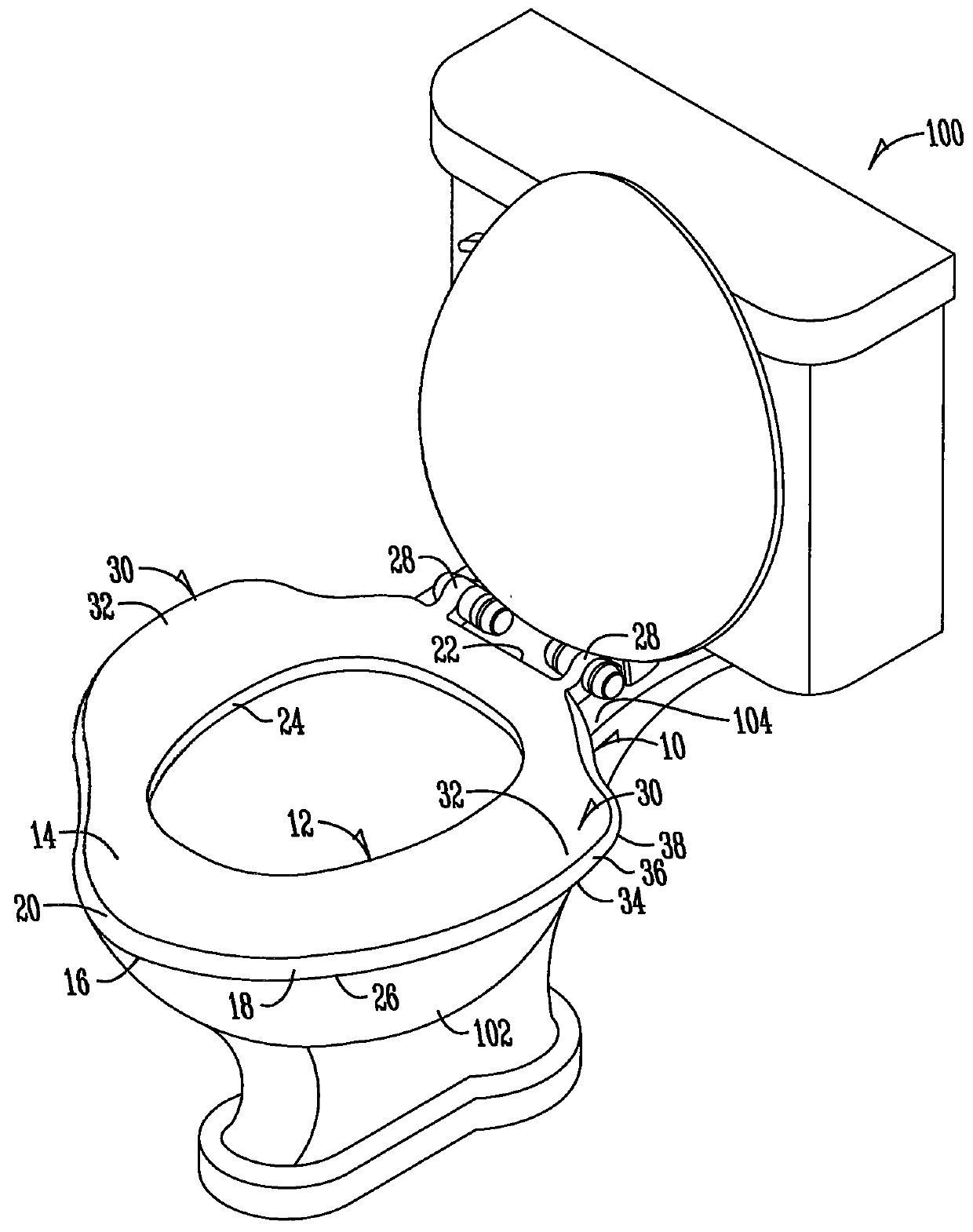
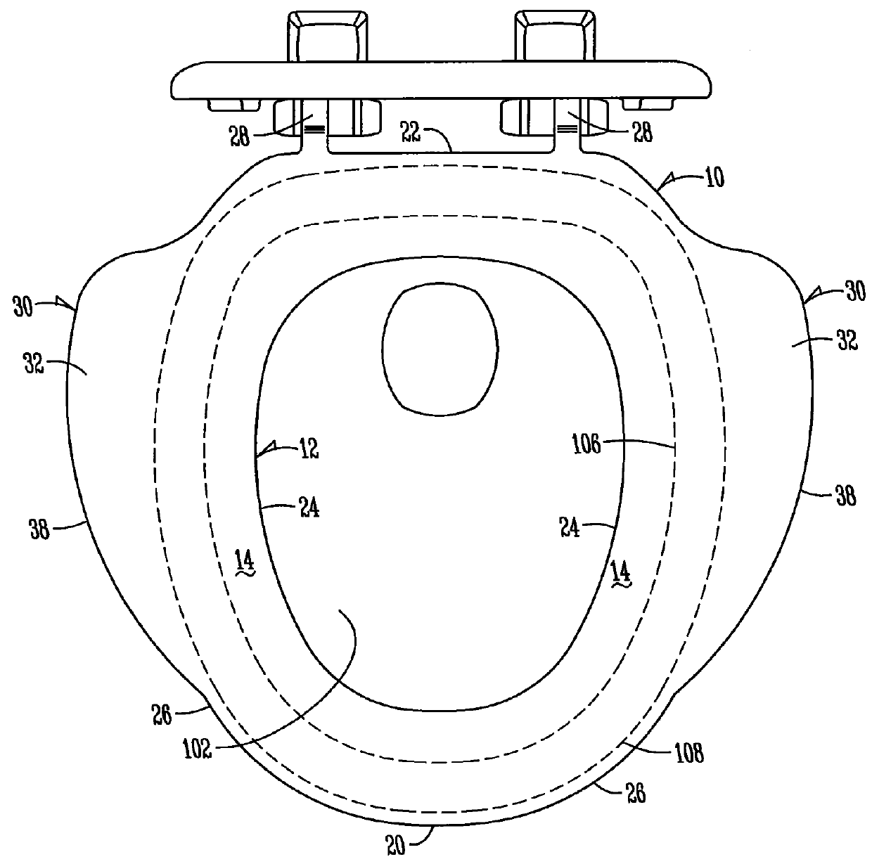
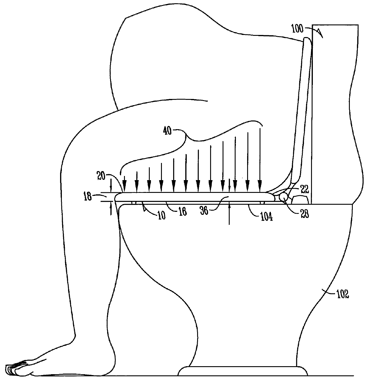
[0017]FIGS. 1-3 of the present invention provide exemplary disclosure and embodiments for a toilet seat configured to provide both skeletal and weight bearing support without limiting an individual's ability to lean forward/or stand from a seated position. The toilet seat 10 is configured for use in combination with a toilet 100 having, for example, a bowl 102 extending generally upwardly terminating in an upper rim 104 spaced between an inner circumference 106 and an outer circumference 108. The toilet seat 10 may be configured with one or more hinge connectors 28 pivotally attaching the seat 10 to the upper rim 104 of the toilet 100. The hinge connectors 28 allow the toilet seat 10 to be articulated between vertical (i.e., an up position) and horizontal (i.e., a down position) positions. The toilet seat 10 is used in the horizontal or down position.
[0018]The toilet seat 10 includes a first portion 12 configured general akin to a traditional style toilet seat. The first portion 12 includes a top surface 14 and opposite bottom surface spaced apart by a thickness 18 of the seat 10. The thickness 18 may be designed to decrease toward the front of the toilet bowl. The top surface 14 and bottom surface 16 terminate at an inner edge 24 which generally approximates the contour of the inner circumference 106 of the toilet 100. The inner edge 24 of the toilet seat 10 may be configured to be cantilevered over the inner circumference 106 of the toilet 100 when located in the down or horizontal position. The top surface 14 and bottom surface 16 also terminate in an outer edge 26 which generally approximates the outer circumference 108 of the upper rim 104 of the toilet bowl 102. The top surface 14 and bottom surface 16 of the first portion 12 of the toilet seat 10 extend generally between the front end 20 which generally approximates the front of the outer circumference 108 of the upper rim 104 of the toilet bowl 102 and the back end 22 which is generally proximate the back of the outer circumference 108 of the upper rim 104 of the toilet bowl 102.
[0019]When the toilet seat 10 is in the horizontal or down position the bottom surface 16 of the first portion 12 is supported by the upper rim 104 of the toilet bowl 102. Thus, according to one embodiment of the invention, the bottom surface 16 of the first portion 12 is in contact, at least at one or more points, with the upper rim 104 of the toilet bowl 102 generally from the back end 22 to the front end 20. For example, one or more bumpers may be configured on the bottom surface 16 of the toilet seat 10 to be in contact with the upper rim 104 of the toilet 100 when the seat 10 is in the down position. When an individual is seated atop the toilet seat 10, the first portion 12 is configured to generally support the bone or skeletal structure of the individual. Notwithstanding the weight of the individual ranging from thin to overweight, the bone structure of the individual generally remains unchanged and therefore is supported by the top surface 14 of the first portion 12. The top surface 14 may be configured with a distal to medial slope (e.g., a decreasing slope from the outer edge 26 toward the inner edge 24.
[0020]The toilet seat 10 is also configured to include a second or outer portion 30, designed according to one aspect of the present invention, to be located between the front end 20 and back end 22 of the first portion 12. The second or outer portion 30 includes a top surface 32 integral with the top surface 14 of the first portion 12 and a bottom surface 34 integral with the bottom surface 16 of the first portion 12. The top surface 32, like the top surface 14 of the first portion 12, may be configured with a distal to medial slope (e.g., a decreasing slope from outward to inward). In one aspect of the invention, the thickness 36 of the second or outer portion 30 is configured similar to the thickness 18 of the first portion 12. In another embodiment the thickness 36 of the second or outer portion may also be greater than the first portion 12.
[0021]The top surface 32 and bottom surface 34 of the second portion 36 terminate in an outer edge 38. The outer edge 38 of the second or outer portion 30 extends outward from the outer circumference 108 of the upper rim 104 of the toilet bowl 102 so that the seat 10 has a width generally greater than the width of the first portion 12. When the toilet seat 10 is in the down or horizontal position, the second or outer portion 30 is cantilevered out from the outer circumference 108 of the upper rim 104 of the toilet bowl 102. Thus, the outer edge 38 of the second or outer portion 30 extends generally outwardly (i.e., away from the outer circumference 108 of the upper rim 104) from the back end 22 of the first portion 12, curves radially to generally follow the contour the outer circumference 108 of the upper rim 104 of the toilet bowl 102, and extends inwardly toward the first portion 12 (i.e., toward the outer circumference 108 of the upper rim 104) approximating the outer circumference 108 of the upper rim 104 of the toilet bowl 102.
[0022]The second or outer portion 30 is generally configured to widen the first portion 12 of the toilet seat 10 between the back end 22 and the front end 20. In a preferred aspect of the invention, the second or outer portion 30 widens the first portion 12 closer to the back end 22 than the front end 20. For example, the outer edge 38 of the second or outer portion 30 closer approximates the outer circumference 108 of the upper rim 104 of the toilet bowl 102 as the outer edge 38 extends closer to the front end 20 of the seat 10. For applications where the seat is designed to fit in the typical public restroom stall the outer portion typically extends a maximum of 2 inches
[0023]According to one design, the front end of the first portion 12 is not widened by the second or outer portion 30 and thereby maintains an outer edge that generally approximates the contour of the outer circumference 108 of the outer rim 104 of the toilet bowl 102. The second or outer portion 30 is configured to support generally the lateral fat or weight of an individual seated atop a toilet seat 10 while the first portion 12, as previously indicated, is configured to support the bone or skeletal structure of the individual.
[0024]In use or operation, the features, functions and design/configuration of the toilet seat 10 are further defined. In the horizontal or down position, the toilet seat 10 has a first portion 12 with a bottom surface 16 support by the upper rim 104 of the toilet bowl 102. The toilet seat 10 may be configured so that the bottom surface 16 of the first portion 12 is in contact with the upper rim 104 of the toilet bowl 102 from the back end 22 to the front end 20 whereas the second or outer portion 30 is cantilevered over the outer circumference 108 of the outer rim 104 of the toilet bowl 102. The present invention also contemplates that one or more strengthening ribs or reinforcements may be integrally formed on or in the second or outer portion 30 and the first portion 12 for supporting the forces on the second or outer portion 30 when cantilevered over the outer circumference 108 of the upper rim 104 of the toilet bowl 102.
[0025]As an individual sits atop the toilet seat 10, particularly an overweight person, the top surface 14 of the first portion 12 supports generally the bone or skeletal structure of the individual. Depending on the obesity of the individual, the lateral fat may extend inward and outward away from the skeletal or bone structure of the individual. Generally, a majority of the lateral fat is carried outwardly as opposed to inwardly. And a majority of the lateral fat will generally extend outwardly from the rear of the person not the person's sides. Thus the outer portion of the seat is designed with the maximum overhang beyond the toilet below rim starting as close to the back end 22 as practical.
[0026]The second or outer portion 30 supports the lateral fat extending outward from the bone or skeletal structure of the individual. The top surface 14 of the first portion 12 and the top surface 32 of the second or outer portion 30 create pressure or, more particularly, a moment of pressure 40 on the underside of the individual's legs. Increasing the moment of pressure 40 on the underside of the individuals legs towards his/her knees increases the difficulty of leaning forward and elevating from a seated to a standing position. Therefore, the outer edge of 38 of the second or outer portion 30 narrows to generally proximate the contour of the outer circumference 108 of the upper rim 104 of the toilet bowl 102 toward the front end 20 of the toilet seat 10 to minimize the moment of pressure 40 acting upward on the underside of the individuals legs to not inhibit the individual's ability to lean forward and elevate to a standing from a seated position.
[0027]The second or outer portion 30 in combination with the first portion 12 generally near the back end 22 of the toilet seat 10, as previously indicated, provides support for both the skeletal and lateral fat of the individual. These support points helps maintain and improve compression of the ischial tuberosity, the sciatic nerve and lower back without creating an unwanted upward pressure or moment 40 on the underside of the forward portion of the individuals legs thereby preventing or inhibiting the ability of the individual to lean forward and stand from the seated position. Conversely, widening the toilet seat 10 near the front end 20 creates a moment of pressure 40 on the underside of the individuals legs, particularly near his/her knees, that can inhibit and even prevent an individual from being able to lean forward and elevate from the seated position to a standing position. Therefore, the present invention provides both skeletal and weight bearing support without limiting an individual's ability to lean forward and/or stand from a seated position atop the toilet seat 10.
[0028]Other concerns with widening the front end 20 of the toilet seat 10 include limiting or even inhibiting the ability of the individual while seated atop the toilet seat 10 from being able to touch the ground with his or her feet and thereby control movement while seated, lean forward and even rise to the standing position. The present invention also contemplates that the toilet seat 10 may be configured as a basic circular seat where the seat approximates the contour of the outer and inner circumference of the toilet bowl without a gap in the front, an open front seat that includes a gap or opening in the front of the seat, or an elongated seat which provides additional length between the front and back end.
[0029]The foregoing description has been presented for the purposes of illustration and description. It is not intended to be an exhaustive list or limit the invention to the precise forms disclosed. It is contemplated that other alternative configurations and methods obvious to those skilled in the art are considered included in the invention. The description is merely examples of embodiments. For example, the exact location of the second portion relative to the first portion and the width of the second portion may be configured to provide variations or alternatives. In addition, the toilet seat style may be configured to provide other variations or alternatives. It is understood that any other modifications, substitutions, and/or additions may be made, which are within the intended spirit and scope of the disclosure. From the foregoing, it can be seen that the exemplary aspects of the disclosure accomplishes at least all of the intended objectives.

PUM

no PUM

Description & Claims & Application Information

We can also present the details of the Description, Claims and Application information to help users get a comprehensive understanding of the technical details of the patent, such as background art, summary of invention, brief description of drawings, description of embodiments, and other original content. On the other hand, users can also determine the specific scope of protection of the technology through the list of claims; as well as understand the changes in the life cycle of the technology with the presentation of the patent timeline. Login to view more.

Similar technology patents

Electronic device including battery

Owner:SAMSUNG ELECTRONICS CO LTD

Apparatus for damping vibration

ActiveUS20180187734A1Decrease thicknessOptimize vibration and noise damp effectNon-rotating vibration suppressionShock absorbersEngineering
Owner:KOREA ADVANCED INST OF SCI & TECH

Soft power wireless transmission induction plate

InactiveUS20150102682A1Decrease thicknessTransformersCircuit arrangementsWireless power supplyInduction coil
Owner:COREMATE TECH CO LTD

Classification and recommendation of technical efficacy words

  • Decrease thickness

Magnetic tape and method of manufacturing the same

ActiveUS20160189739A1Decrease thicknessIncrease lengthBase layers for recording layersTape carriersTotal thicknessPeak area
Owner:FUJIFILM CORP

Receiving Antenna and Wireless Power Receiving Device Including the Same

ActiveUS20160156215A1Improved power transmission efficiencyDecrease thicknessLoop antennas with ferromagnetic coreNear-field transmissionPhysicsReceiver coil
Owner:SCRAMOGE TECH LTD

Semiconductor device

Owner:XIAMEN SANAN INTEGRATED CIRCUIT
Why Eureka
Try Eureka