Adjustment structure of garden shears

a technology of adjustment structure and garden shears, which is applied in the direction of direct reading rulers, cutting implements, distance measurement, etc., can solve the problems of off-centered block b>86/b> becoming prone to contortion, and the holding strength of off-centered block b, so as to achieve the effect of structurally simple and effective alignment of handles

Inactive Publication Date: 2009-08-18
WANG KUANG PIN
View PDF4 Cites 16 Cited by
  • Summary
  • Abstract
  • Description
  • Claims
  • Application Information

AI Technical Summary

Benefits of technology

[0009]The main objective of the invention is to propose an adjustment structure of garden shears that can solve the problems described above; it uses an aligning lever disposed on the outer surface of the outer tube to lean against a protruding block, because the protruding block can fit into a cavity on the outer surface of the inner tube and become secured, thereby allowing the inner and outer tubes to be fastened together, the adjustment structure of the invention is structurally simple and effective for aligning handles.
[0011]A further objective of the invention is to propose the formation of a marked unit where the inner tube and the outer tube are joined, so that users can clearly grasp the precision in the movement between the inner tube and the outer tube with the use of said marked unit.

Problems solved by technology

However, because the adjustment structure of the handles are more complex; the off-centered block 86 is made of plastic, and also compounded by the fact that the off-centered block 86 is pushed against the inner wall 811 of the outer tube 81 on only one tilted lateral side to achieve alignment; the off-centered block 86 becomes prone to contortion after a period of usage.
As a result, the holding strength of the off-centered block 86 becomes insufficient over time, and thus it is necessary to improve the adjustment structure of the handles in a prior art.

Method used


Image

  • Adjustment structure of garden shears
  • Adjustment structure of garden shears
  • Adjustment structure of garden shears

Examples


Embodiment Construction

[0026]FIGS. 1 to 6 illustrate the selected embodiments of this invention; the embodiments only serve the purpose of elucidation and are not to be used to limit the scope of the invention in any ways.

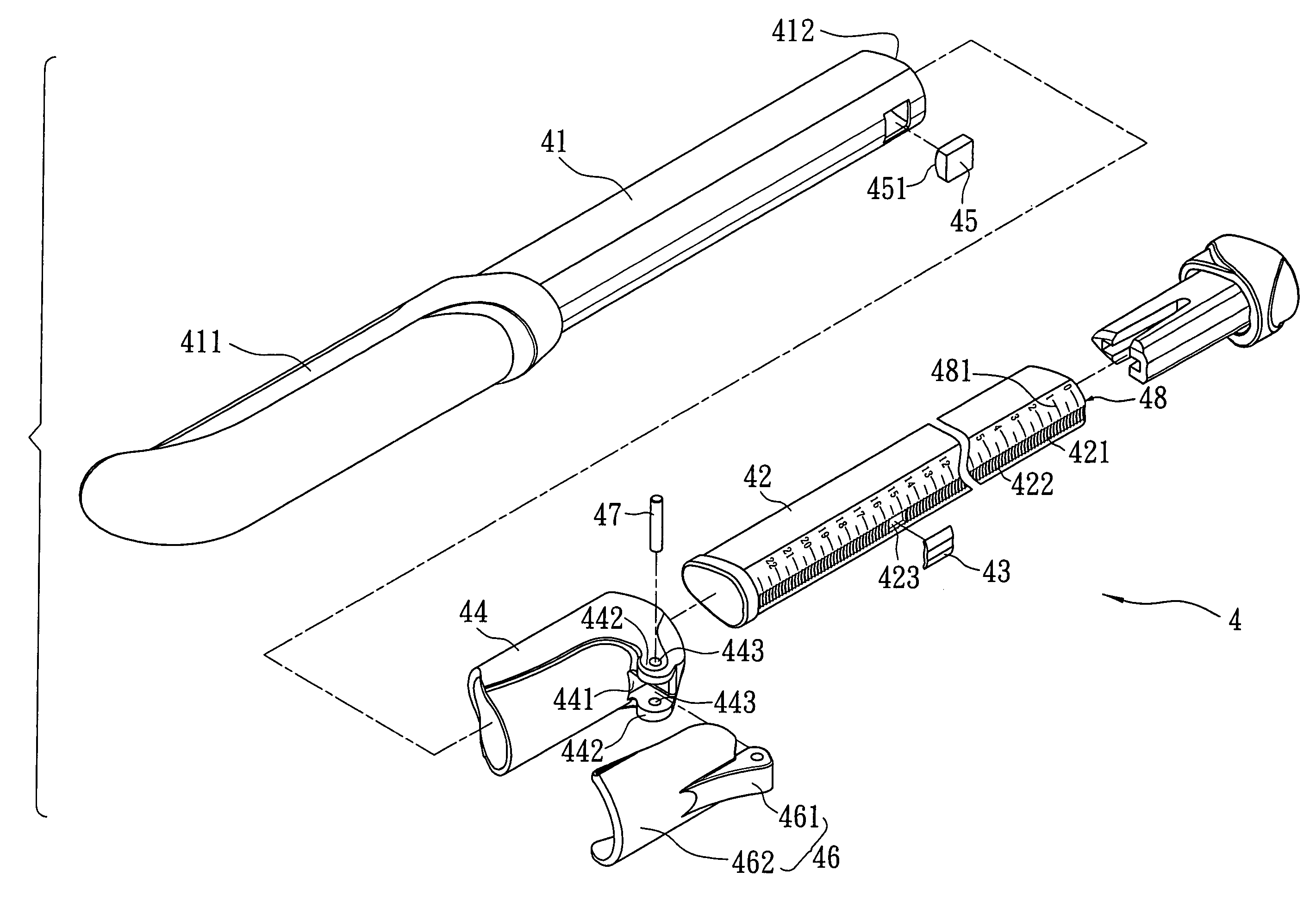
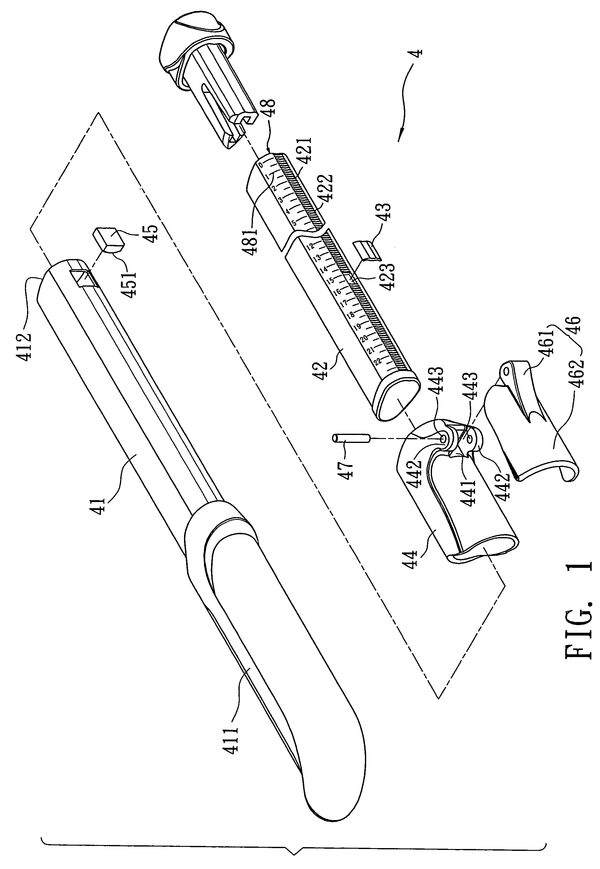
[0027]The adjustment structure of garden shears of this embodiment, as shown in FIG. 1 and FIG. 2, comprising:

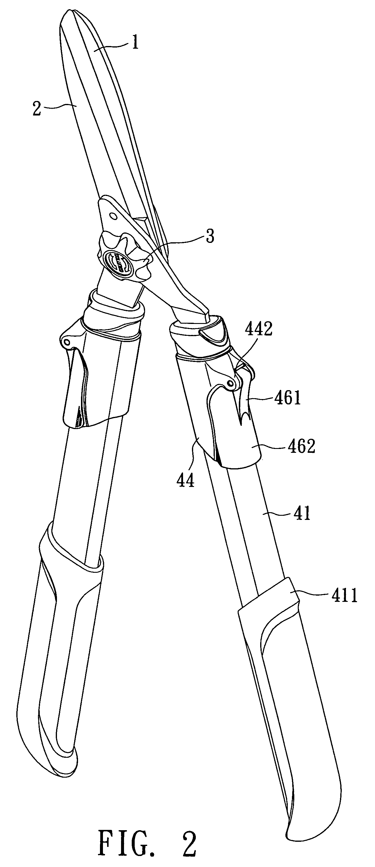
[0028]a first blade 1 and a second blade 2 being crossly joined together, said first and second blades 1 and 2 are crossly joined by the use of a removable rotating button 3; in this embodiment, since said first blade 1 and second blade 2 both connect to an identical adjustment structure 4, only one adjustment structure 4 is required as an example for the purpose of further explanation, said adjustment structure 4 comprising:

[0029]an outer tube 41, one end of said outer tube 41 being disposed with a grab handle 411.

[0030]an inner tube 42 being fitted into said outer tube 41, a trough 421 being disposed on the outer surface of said inner tube 42, the inner surface of said trough 4...


PUM


Abstract

An adjustment structure of garden shears, which utilizes an aligning lever disposed on the outer surface of an outer tube to support a protruding block; because the protruding block can be fitted into a trough on the outer surface of the inner tube and become secured, the inner tube and the outer tube become fastened together as a result. Moreover, a marked unit is disposed where said inner tube and outer tube are joined, thereby allowing the invention to have a structurally simple handle that can be aligned effectively, which in turn allows users to grasp the precision in the movement between said inner tube and outer tube.

Description

BACKGROUND OF THE INVENTION[0001]1. Field of the Invention[0002]The invention relates to an adjustment structure of garden shears. More particularly, the invention relates to an adjustment structure having a simple structure and being effective for aligning handles.[0003]2. Description of Prior Art[0004]FIG. 7 shows the adjustment structure of handles in a prior art; an end of outer handle 81 of the handle 8 is disposed with a fastening member for the outer tube 82, the fastening member for the outer tube 82 allows a base member 83 to fit through, so that said base member 83 can be rotated on the fastening member for the outer tube 82; said base member 83 is joined with a rod 84 with square cross section, and a carrier member 85 is fitted on said rod 84; said carrier member 85 has a square opening 851 for said rod 84 to fit through, thus making carrier member 85 rotate along with said rod 84 when it is rotated.[0005]The carrier member 85 has a protruding pole 852, the end of protrud...

Claims


Application Information

Patent Timeline
Patent Type & Authority Patents(United States)
IPC IPC(8): B25G1/00B25G1/04B25G3/00G01B3/08
CPCB25G1/04A01G3/0251F16B7/1454Y10T403/32501Y10T16/473Y10T403/20
Inventor WANG, KUANG-PIN
Owner WANG KUANG PIN
Why Eureka
Try Eureka