Magnet valve

a magnet valve and valve body technology, applied in the direction of valve operating means/release devices, magnetic bodies, brake systems, etc., can solve the problems of adverse valve behavior and damage, and achieve the effect of improving valve performan

Inactive Publication Date: 2009-08-18
ROBERT BOSCH GMBH
View PDF6 Cites 13 Cited by
  • Summary
  • Abstract
  • Description
  • Claims
  • Application Information

AI Technical Summary

Benefits of technology

[0007]The magnet valve of the invention has the advantage over the prior art that centering means are present, which are disposed on the tappet in such a way that the restoring spring is centered and radially guided from inside over a substantial portion of its length and is thus stabilized. Flow forces that act on the turns of the restoring spring can thus advantageously be prevented from causing lateral deflection of the restoring spring, or the restoring spring can be prevented from lifting from a contact, and the turns of the restoring spring can be prevented from moving relative to one another or being set to vibrating. In particular, a spring end resting only axially on a valve body is centered and stabilized by the centering means, without adversely affecting the capability of installing and adjusting the magnet valve.
[0008]By the provisions and refinements disclosed, advantageous improvements to the magnet valve recited in the independent claim are possible. It is especially advantageous that the centering means are embodied as at least two axially extending centering ribs, originating at the spring guide of the tappet, which lengthen the circumference of the spring guide beyond a tappet cone to inside a transition region of the tappet. Because of the at least two axial centering ribs, the restoring spring can advantageously be guided radially from inside over a longer distance, so that the restoring spring is centered and stabilized over virtually its entire length. Moreover, the flow behavior through the valve assembly is hardly affected by the embodiment of the centering means as axial centering ribs. The dimensions of the at least two axial centering ribs are adapted in the radial direction to the inside diameter of the restoring spring, so that the spring end resting only axially on the valve body is guided radially on the inside as far as possible. The at least two axial centering ribs are advantageously defined in such a way that a flow force component acting circumferentially through the fluid does not cause a rotational motion of the tappet. The length and shape of the axial centering ribs in the direction of a tappet dome are adapted to the usage conditions and prevent an adverse effect on the flow behavior through the valve assembly, and prevent spring parts or turns from catching on the centering ribs; as a result, a constant spring force action on the tappet and a controllable valve behavior can be assured.
[0011]Alternatively, the centering means can be embodied as a lengthened spring guide, which shortens the tappet cone and the transition region of the tappet, and the tappet cone is shifted in the direction of a tappet dome, and the restoring spring is centered and radially guided from inside over the substantial portion of its length.

Problems solved by technology

Because of the frictional forces generated, the valve behavior can be adversely affected, and the tappet 20 may be damaged by the spring ends, which may have burrs.

Method used


Image

  • Magnet valve
  • Magnet valve
  • Magnet valve

Examples


Embodiment Construction

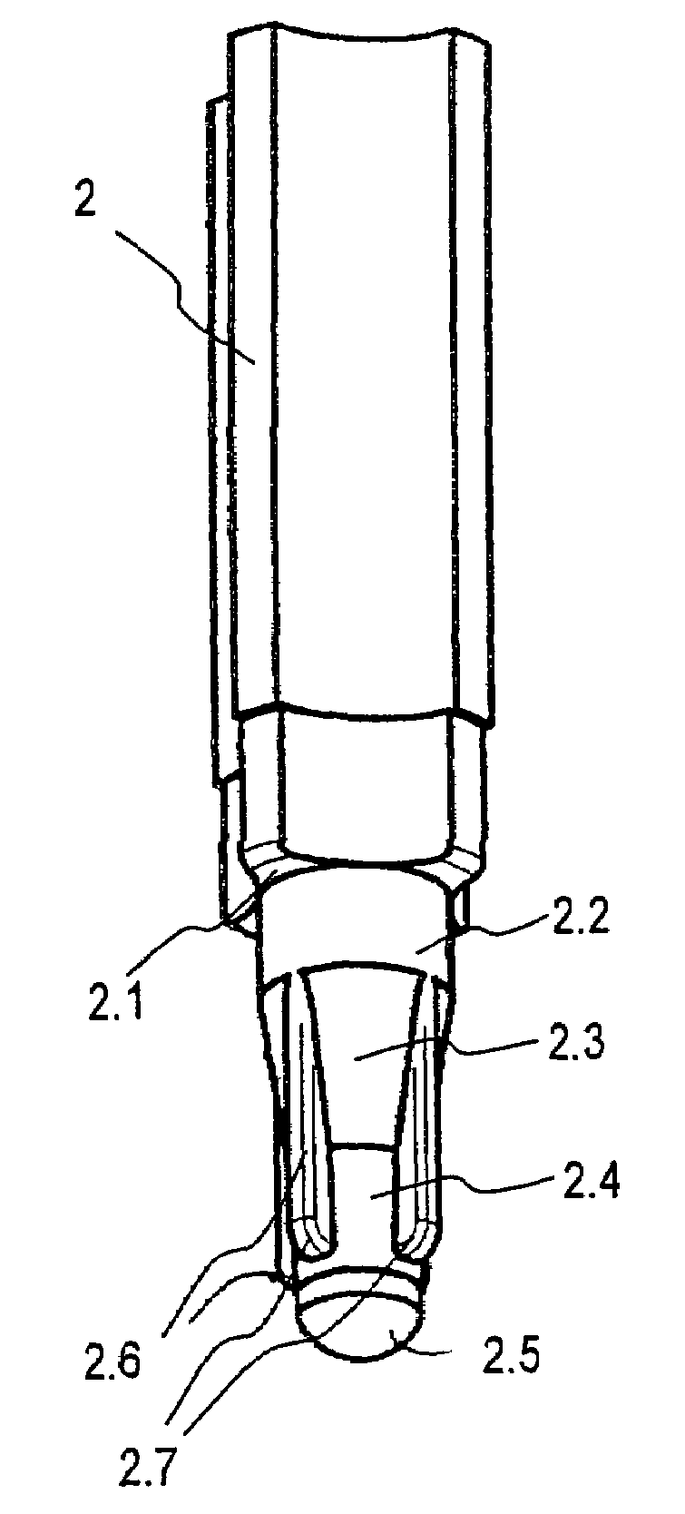
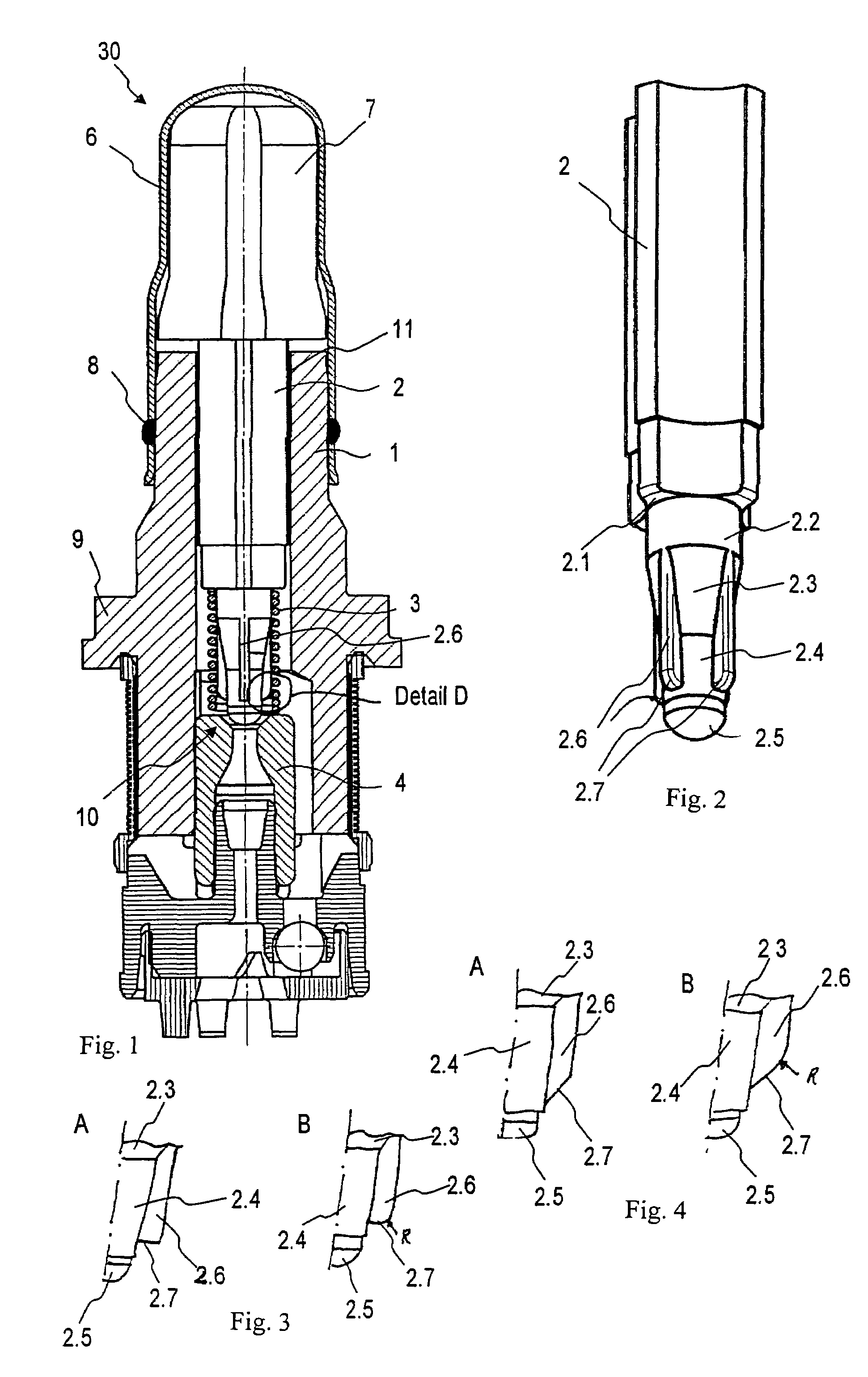
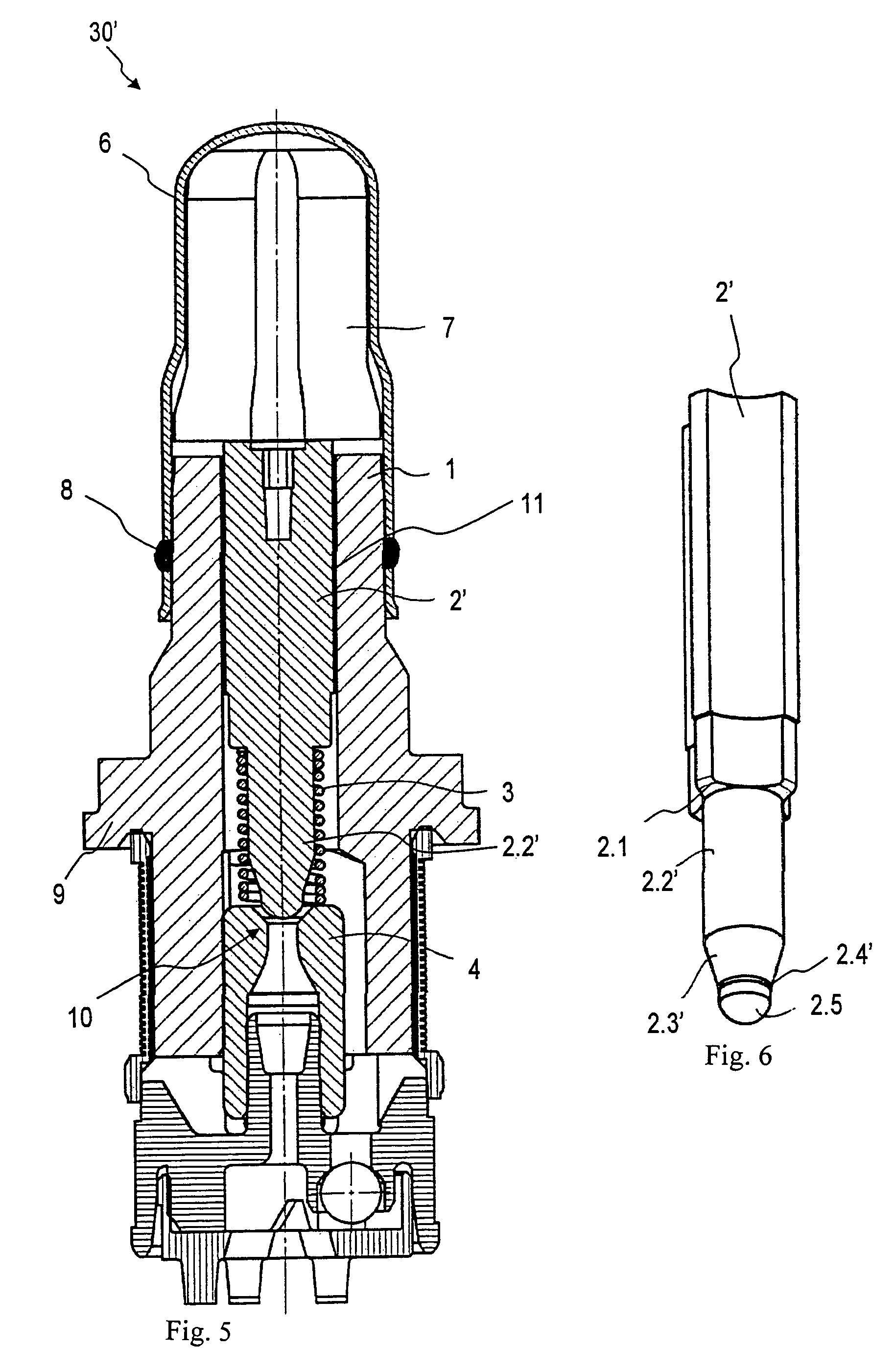
[0020]As can be seen from FIG. 1, a magnet valve 30 of the invention, besides a magnet assembly, not shown, has a valve cartridge, which analogously to the conventional magnet valve 40 of FIG. 7 includes a capsule 6, a valve insert 1, a tappet 2, a restoring spring 3, and an armature 7. In the production of the magnet valve 30, the capsule 6 and the valve insert 1 of the valve cartridge are joined together by pressing, and by means of a sealing weld 8, the valve cartridge is hydraulically sealed off from the atmosphere. In addition, the valve insert 1 absorbs the pressure forces that occur in the hydraulic system and conducts them onward via a calked flange 9 to a calked region, not shown, on a fluid block. The valve insert 1 also receives the so-called valve body 4, which includes a valve seat 10 into which the tappet 2 plunges in sealing fashion in order to accomplish the sealing function of the magnet valve 30. As also seen from FIG. 1, the tappet 2 is guided via a tappet guide 1...


PUM


Abstract

The invention relates to a magnet valve, having a valve insert and a tappet guided movably in the valve insert via a tappet guide, which tappet is braced on a valve body via a restoring spring resting a contact face of the tappet, and the restoring spring is guided radially from inside on one end by a spring guide of the tappet, the spring guide adjoining the contact face. According to the invention, centering means are present, which are disposed on the tappet in such a way that the restoring spring is centered and radially guided from inside over a substantial portion of its length.

Description

REFERENCE TO FOREIGN PATENT APPLICATION[0001]This application is based on German Patent Application No. 10 2006 004 530.0 filed 1 Feb. 2006, upon which priority is claimed.BACKGROUND OF THE INVENTION[0002]1. Field of the Invention[0003]The invention is directed to an improved magnet valve suitable for use, for example, in hydraulic fluid systems.[0004]2. Description of the Prior Art[0005]A conventional magnet valve, in particular for a hydraulic unit, which is used for instance in an antilock system (ABS) or a traction control system (TCS) or an electronic stability program (ESP) system is shown in FIG. 7. As seen from FIG. 7, the conventional magnet valve 40, which is open when without current, has, besides a magnet assembly 5 with a cover disk 12, a valve cartridge, which includes a capsule 6, a valve insert 1, a tappet 20, a restoring spring 3, and an armature 7. In the production of the magnet valve 40, the capsule 6 and the valve insert 1 of the valve cartridge are joined toget...

Claims


Application Information

Patent Timeline
Patent Type & Authority Patents(United States)
IPC IPC(8): F16K31/02
CPCB60T8/363F16K31/0658F16K1/36F16K31/0693F16K31/0655
Inventor SPEER, HARALDMICHL, THOMASSCHINDLER, RALFKRATZER, DIETMARVIER, ELMARSCHUSTER, GERHARD
Owner ROBERT BOSCH GMBH
Why Eureka
Try Eureka