Fuel injection controller of engine

a technology of fuel injection controller and internal combustion engine, which is applied in the direction of electric control, fuel injection apparatus, charge feed system, etc., can solve the problems of affecting the operation state of the engine, the possibility of reducing the rotation speed of the engine, and the inability of the technology to respond to the above-mentioned conditions, etc., to achieve the effect of not adversely affecting the operating state of the engin

Active Publication Date: 2006-02-09
DENSO CORP
View PDF5 Cites 7 Cited by
  • Summary
  • Abstract
  • Description
  • Claims
  • Application Information

AI Technical Summary

Benefits of technology

[0009] It is therefore an object of the present invention to provide a fuel injection controller of an internal combustion engine capable of setting an optimum fuel injection quantity without adversely affecting an operating state of the engine even in the case where the series of operations, of rapidly opening a throttle valve from a certain throttle opening degree and then rapidly closing the throttle valve, occurs in an extremely short time within a combustion cycle of the engine.
[0010] According to one aspect of the present invention, a fuel injection controller of an internal combustion engine performs stroke determination based on a crank angle signal, which is detected by crank angle detector based on rotation of a crankshaft of the engine. The fuel injection controller calculates a fuel injection quantity based on various parameters including a throttle opening degree sensed by a throttle opening degree sensor. A fuel injection valve supplies the fuel injection quantity in accordance with the crank angle signal. The fuel injection controller compulsorily stops the supply of the fuel injection quantity to avoid an over-rich mixture condition if the series of operations, of rapidly opening a throttle valve from a certain throttle opening degree and of rapidly closing the throttle valve, occurs within a predetermined short time. The supply of the fuel injection quantity is necessary to maintain an operating state of the engine if drawing of an air intake quantity defined by the series of operations of the throttle valve overlaps with at least one-third of an intake stroke in one combustion cycle of the engine. Therefore, in such a case, the fuel injection controller removes the compulsory stoppage of the supply of the fuel injection quantity. Thus, suitable fuel injection quantity can be set to avoid an adverse effect on the operating state of the engine, even if the series of operations, of rapidly opening the throttle valve from a certain throttle opening degree and then rapidly closing the throttle valve, occurs in an extremely short time, shorter than one combustion cycle of the engine.

Problems solved by technology

If the processing ability of the CPU of an electronic control unit at the time when this technology was made is taken into consideration, then it would not have been possible for the above technology to consider the case where a series of operations, such as rapidly opening a throttle valve from a certain throttle opening degree and then rapidly closing the throttle valve, occurs in an extremely short time within one combustion cycle of the engine.
Therefore, this technology cannot respond to an over-rich mixture condition, which can be caused by asynchronous fuel injection performed in accordance with the change in the throttle opening degree when the acceleration is required in the first stage by a driver and the throttle valve is rapidly opened.
As a result, there is a possibility of reduction of engine rotation speed or engine stall.
However, in some cases, the over-rich mixture condition is not necessarily caused by the asynchronous fuel injection even in the case where the series of operations, namely, rapidly opening the throttle valve from a certain throttle opening degree and then rapidly closing the throttle valve, occurs in an extremely short time within a combustion cycle of the engine.
There is also the possibility that an operating state of the engine is adversely affected if the fuel supply quantity is reduced or cut in a uniform manner.

Method used


Image

  • Fuel injection controller of engine
  • Fuel injection controller of engine
  • Fuel injection controller of engine

Examples


Embodiment Construction

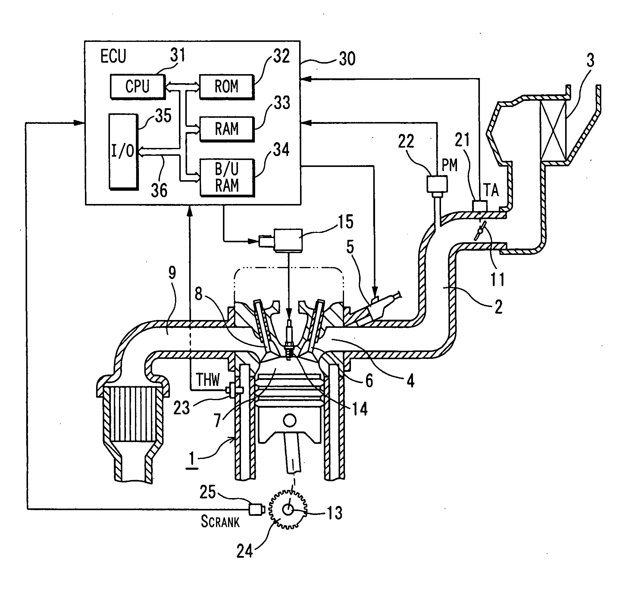
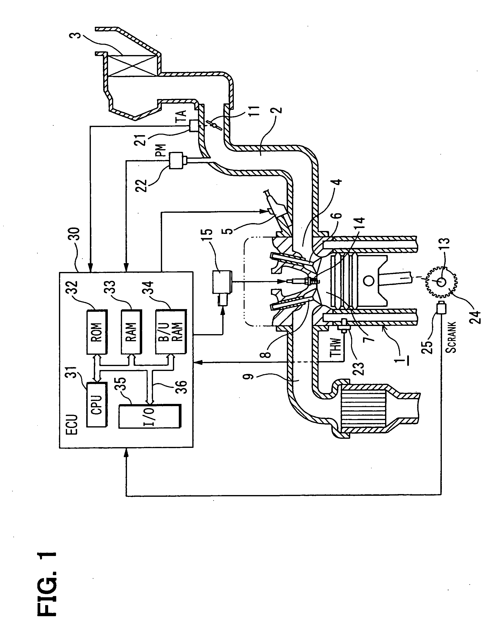
[0018] Referring to FIG. 1, a fuel injection controller applied to an internal combustion engine according to an example embodiment of the present invention is illustrated.

[0019] The engine 1 shown in FIG. 1 is a four-cycle single-cylinder engine. Air is introduced into an intake passage 2 of the engine 1 through an air cleaner 3. A throttle valve 11 is disposed in the intake passage 2. The throttle valve 11 is opened and closed in accordance with an accelerator manipulation amount or the like provided by a driver (operator). A quantity of the intake air drawn into the intake passage 2 is regulated by opening and closing the throttle valve 11. Fuel, which is pressure-fed by a fuel pump (not shown) from a fuel tank (not shown) and a pressure of which is regulated by a pressure regulator (not shown), is injected and supplied near an intake port 4 of the engine 1 by an injector (fuel injection valve) 5 disposed in the intake passage 2 in accordance with the air intake quantity. A mixt...


PUM


Abstract

An electronic control unit compulsorily stops supply of a fuel injection quantity, which is calculated based on various parameters including a throttle opening degree, performed by an injector in accordance with a crank angle signal if a series of operations, of rapidly opening a throttle valve from a certain throttle opening degree and then rapidly closing the throttle valve, occurs within a predetermined time in one combustion cycle of an internal combustion engine after completion of stroke determination. The electronic control unit removes the compulsory stoppage of the supply of the fuel injection quantity if drawing of an air intake quantity overlaps with at least one-third of an intake stroke in one combustion cycle of the engine.

Description

CROSS REFERENCE TO RELATED APPLICATION [0001] This application is based on and incorporates herein by reference Japanese Patent Application No. 2004-227042, filed on Aug. 3, 2004, and Japanese Patent Application No. 2005-119812 filed on Apr. 18, 2005. BACKGROUND OF THE INVENTION [0002] 1. Field of the Invention [0003] The present invention relates to a fuel injection controller of an internal combustion engine for calculating a fuel injection quantity in a combustion cycle based on a crank angle signal, which is detected in accordance with an angular position corresponding to rotation of a crankshaft of the engine, and for performing fuel injection control. [0004] 2. Description of Related Art [0005] In an independent air intake internal combustion engine, a basic fuel injection quantity is set in accordance with an intake pressure, a throttle opening degree, an engine rotation speed or the like. A final fuel injection quantity is calculated by correcting the basic fuel injection qu...

Claims


Application Information

Patent Timeline
Patent Type & Authority Applications(United States)
IPC IPC(8): F02M51/00F02B77/08
CPCF02B29/083F02D11/106F02D2200/0404F02D2041/002F02D41/009Y02T10/40
Inventor OKOCHI, YASUHIRO
Owner DENSO CORP
Why Eureka
Try Eureka