Particle sensor and particle sensing method

a particle sensor and particle technology, applied in the field of sensors, can solve the problems of excessive pm2.5 pollution, long user wait time, and relatively low readings, and achieve the effect of stable readings and no adverse effects on the flow through the sensor

Active Publication Date: 2020-04-16
KONINKLJIJKE PHILIPS NV
View PDF4 Cites 8 Cited by
  • Summary
  • Abstract
  • Description
  • Claims
  • Application Information

AI Technical Summary

Benefits of technology

[0012]There is therefore still a need for a particle sensor which can provide a stable reading more quickly when detecting particles at low concentrations, and without adversely affecting the flow through the sensor.

Problems solved by technology

Especially in China, excessive PM2.5 pollution has become a common problem in the last decade.
Furthermore these optical sensors only detect particles in a certain volume of the air so that relatively low readings are obtained.
The long time to reach a stable value means the user has to wait a long time before a stable and reliable reading is obtained.
This would require larger air pumps which would increase the size of the sensor.
A sensor that can selectively sense specific particles like pollen is likely to face problems in practice due to their low concentration levels in the air.
However, this introduces an additional flow restriction, which affects the general fluid flow through the sensor.

Method used


Image

  • Particle sensor and particle sensing method
  • Particle sensor and particle sensing method
  • Particle sensor and particle sensing method

Examples


Embodiment Construction

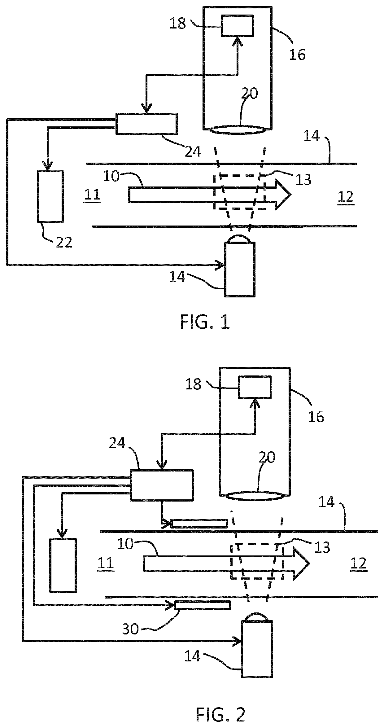
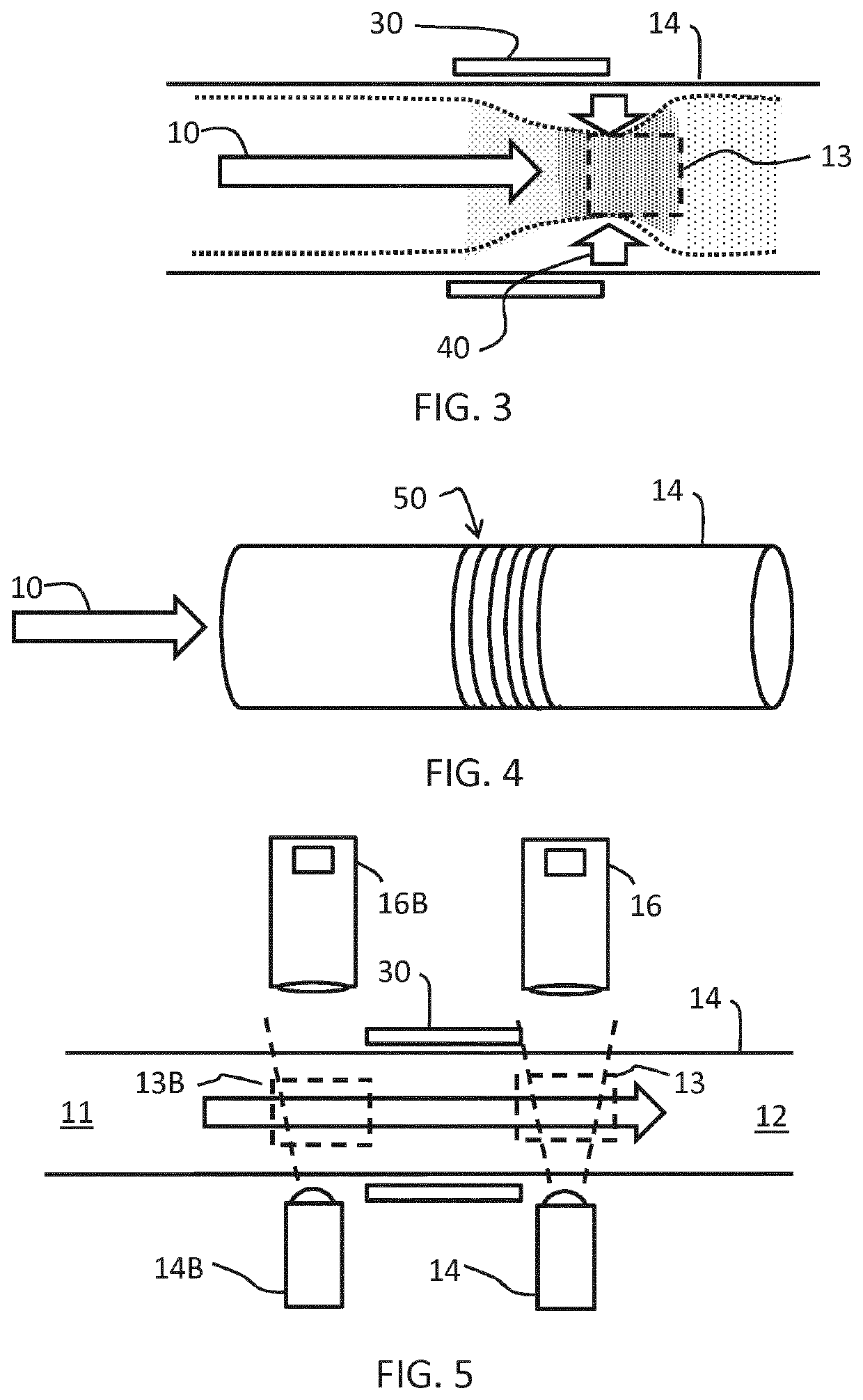
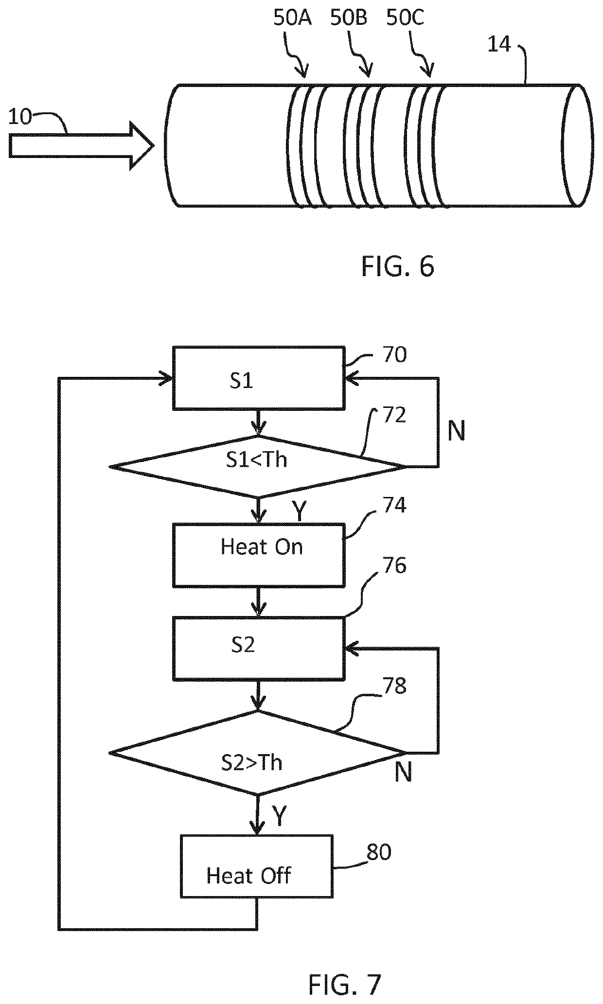
[0057]The invention provides a particle sensing system for sensing particles entrained in a fluid. The system comprises a flow channel having a longitudinal direction along which the fluid is to be passed, a heating arrangement for heating the fluid and thereby applying a positive thermophoretic force on the fluid in a direction perpendicular to the longitudinal direction of the flow channel and a sensor for sensing the particles in the fluid after heating by the heating arrangement. The sensor has a detection volume, and the thermophoretic effect is used to increase the particle concentration in the detection volume.

[0058]The use of thermophoresis is known for inducing particles in air to deposit on the surface of a mass sensor. For example reference is made to I. Paprotny, F. Doering, P. A. Solomon, R. M. White, and L. A. Gundel, “Microfabricated air-microfluidic sensor for personal monitoring of airborne particulate matter”: Design, fabrication, and experimental results, Sensors ...


PUM

PropertyMeasurementUnit
diameteraaaaaaaaaa
concentrationsaaaaaaaaaa

Abstract

A particle sensing system is for sensing particles entrained in a fluid. The system comprises a flow channel having a longitudinal direction along which the fluid is to be passed, a heating arrangement for heating the fluid and thereby applying a positive thermophoretic force on the fluid in a direction perpendicular to the longitudinal direction of the flow channel and a first sensor for sensing the particles in the fluid after heating by the heating arrangement. The thermophoretic force increases the concentration of the particles at the first sensor.

Description

FIELD OF THE INVENTION[0001]This invention relates to sensors for detecting particles in a fluid flow and methods for detecting particles using such sensors.BACKGROUND OF THE INVENTION[0002]Airborne particle pollution, especially particle matter having a diameter less than 2.5 μm (named “PM2.5”), is a big concern for countries like China, where the speed of industrialization stretches the boundaries of regulatory requirements relating to air quality.[0003]As a consequence of increasing consumer empowerment, the demand for information about the air quality of living spaces is increasing. Especially in China, excessive PM2.5 pollution has become a common problem in the last decade. This problem is also validated by continuous measurements in various Chinese cities. The data is publicly available and can be simultaneously monitored by mobile phone applications or through the web.[0004]Availability of this data as well as continuous national and international media attention has created...

Claims


Application Information

Patent Timeline
Patent Type & Authority Applications(United States)
IPC IPC(8): G01N1/40G01N15/06B01L3/00B01L7/00
CPCG01N1/4022B01L2300/1805B01L2300/0627G01N2015/0046B01L2200/0636G01N15/06B01L3/502776G01N2015/0693B01L7/00B01L2400/0451B01L3/502715G01N2015/1486G01N15/1459G01N2001/2223B01L3/502761B01L7/525B01L2300/1827
Inventor KELLY, DECLAN PATRICKSCHEJA, MICHAEL MARTINCHEN, SHUANGRONDA, CORNELIS REINDER
Owner KONINKLJIJKE PHILIPS NV
Why Eureka
Try Eureka