Battery having a Protection from Adjacent Cells in Case of Discharge of a Battery Cell

a battery cell and protection technology, applied in the direction of batteries, cell components, electrical apparatus, etc., can solve the problems of limiting the amount and causing costs, and achieve the effect of reducing the requirements for leaktightness and pressure on the additional valves

Inactive Publication Date: 2014-12-18
ROBERT BOSCH GMBH +1
View PDF4 Cites 7 Cited by
  • Summary
  • Abstract
  • Description
  • Claims
  • Application Information

AI Technical Summary

Benefits of technology

[0018]The routing of the tubes in the discharge tube system is preferably configured in such a way that the pressure surge when a battery cell is relieved is always guided in the direction of an outlet out of the housing. The pressure on the additional valves and hence the requirements on the leaktightness thereof are thereby reduced.

Problems solved by technology

This also limits the amount of waste which arises when remedying the consequences of the relief of a battery cell of a battery and which has to be disposed of, possibly giving rise to costs.

Method used


Image

  • Battery having a Protection from Adjacent Cells in Case of Discharge of a Battery Cell
  • Battery having a Protection from Adjacent Cells in Case of Discharge of a Battery Cell
  • Battery having a Protection from Adjacent Cells in Case of Discharge of a Battery Cell

Examples


Embodiment Construction

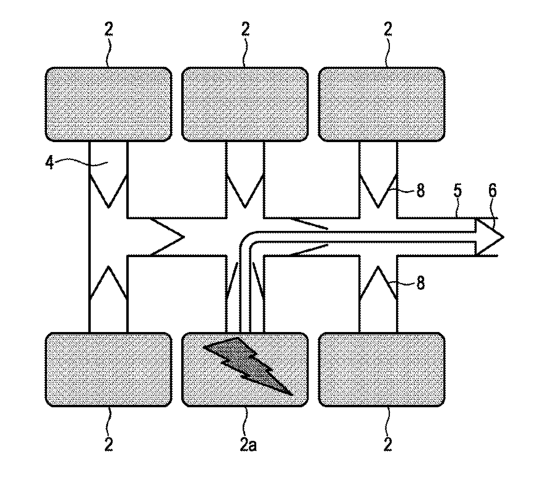
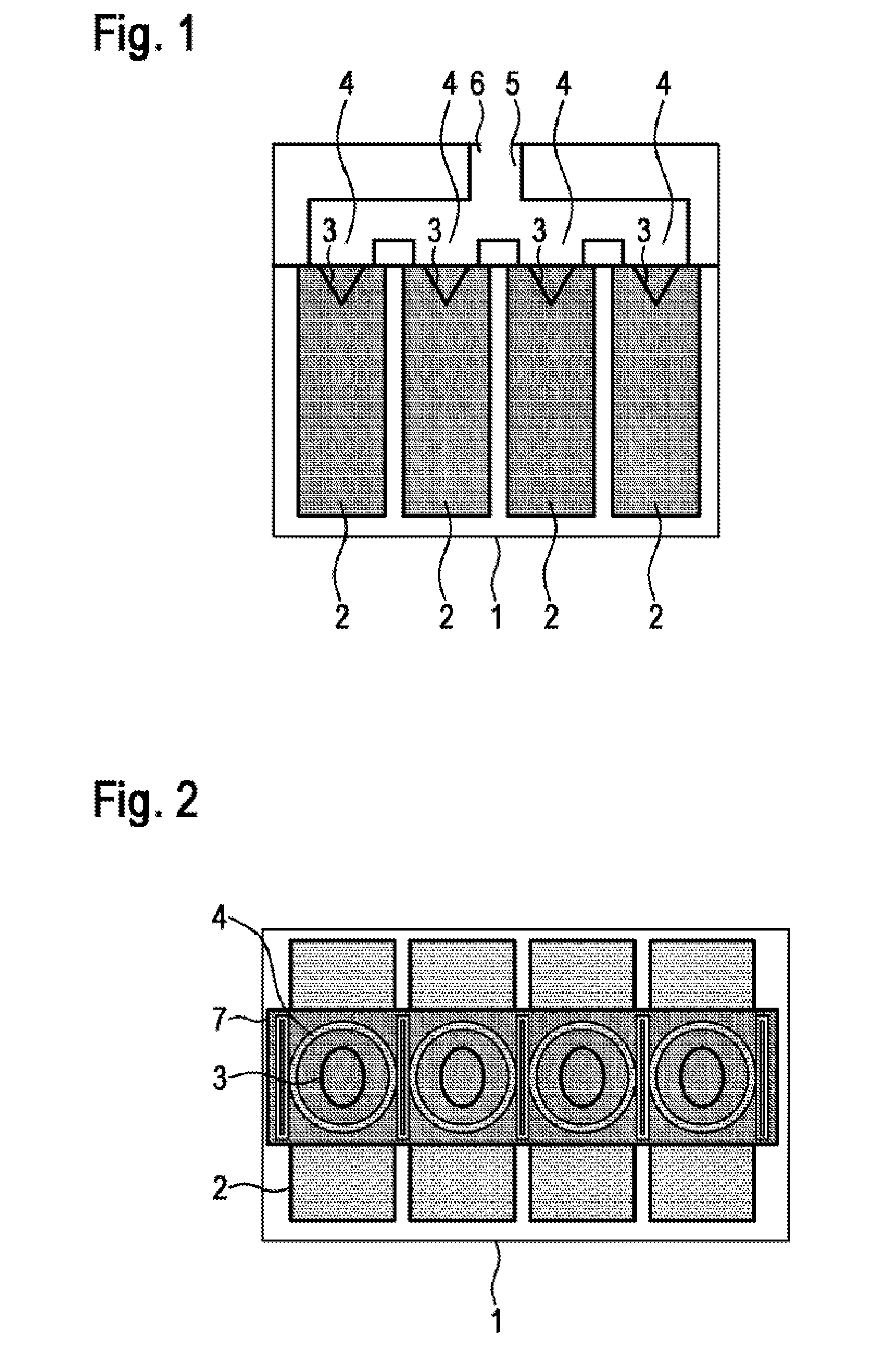
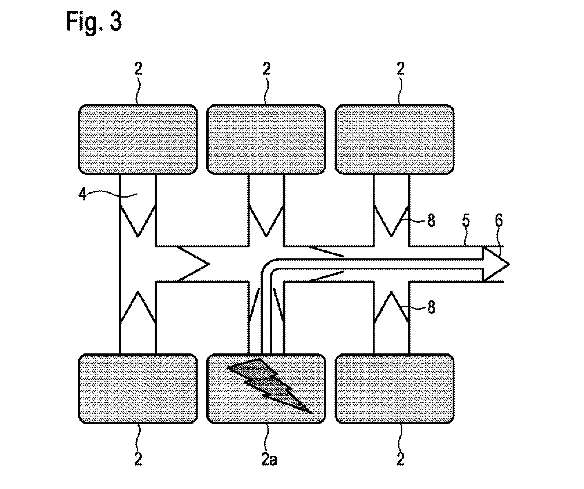
[0024]A battery according to the invention is illustrated schematically in FIGS. 1 and 2. In FIG. 1, the battery is illustrated in a side view, while FIG. 2 shows the same embodiment in a plan view. A plurality of battery cells 2 is arranged in the housing 1, wherein each battery cell 2 has at least one blowoff valve 3. Respective separate connections 4 are mounted over the blowoff valves 3 of the battery cells 2, and these connections are capable of receiving gases released when the battery cells 2 are relieved through the respective blowoff valves 3 and of guiding them to the common discharge conduit 5 of the discharge tube system. Via the common discharge conduit 5 of the discharge tube system, gases released can be fed to an outlet 6 in the housing 1 and removed from the interior of the battery via said outlet. The battery according to the invention is characterized in that a protective film 7 is arranged between the blowoff valves 3 of the battery cells 2 and the respective sep...


PUM

PropertyMeasurementUnit
pressureaaaaaaaaaa
electrically conductiveaaaaaaaaaa
store energyaaaaaaaaaa

Abstract

A battery comprises a housing and a plurality of battery cells arranged in the housing. Each battery cell has at least one discharge valve. The battery further comprises a discharge pipe system for discharging gases released from one, a plurality of or all discharge valves of the battery cells. The discharge pipe system according to the disclosure has a plurality of separate connections for receiving the released gases and a common discharge guide into which the separate connections open and via which the released gases can be discharged out of the housing. The battery is characterized in that a protective film is arranged between the discharge valves of the battery cells and the separate connections of the discharge pipe system so that direct contact of the battery cells to the gases in the discharge pipe system is prevented.

Description

[0001]The present invention relates to a battery which is embodied in such a way that adjacent battery cells are protected from the harmful effects of the gases released when a battery cell is relieved.PRIOR ART[0002]Battery cells that are customarily used in batteries, in particular in lithium-ion batteries, have a safety or blowoff valve which opens when an excessive pressure develops within the battery cell, due to overheating and evaporation of the electrolyte for example, and allows material, generally in the form of gases, to escape from the cell. An explosion of the battery cell body is thereby avoided. The gases released during what is known as the relief of a battery cell are discharged from the battery housing via a discharge tube system in order to prevent contact between the gases, some of which are highly reactive, and other components of the battery. For this purpose, the general practice is for all battery cells of a battery to be connected to a common discharge tube ...

Claims


Application Information

Patent Timeline
Patent Type & Authority Applications(United States)
IPC IPC(8): H01M2/12H01M50/367
CPCH01M2/1241H01M2/1252H01M2220/20Y02E60/10H01M50/317H01M50/3425H01M50/367
Inventor REITZLE, ALEXANDERZIMMERMANN, ULRICH
Owner ROBERT BOSCH GMBH
Why Eureka
Try Eureka