Fluid flow control device and method for use of same

a flow control device and fluid flow technology, applied in drinking water installation, survey, borehole/well accessories, etc., can solve the problems of unreliable, difficult and expensive manufacturing of labyrinth-type flow control devices, and unsuitable sliding sleeve type flow control devices, etc., to achieve the effect of not difficult or expensive to manufactur

Inactive Publication Date: 2006-06-06
HALLIBURTON ENERGY SERVICES INC
View PDF134 Cites 233 Cited by
  • Summary
  • Abstract
  • Description
  • Claims
  • Application Information

AI Technical Summary

Benefits of technology

[0008]The present invention disclosed herein comprises a fluid flow control device for controlling the inflow of formation fluids in completions requiring sand control and a method for use of the same. The fluid flow control device of the present invention is not difficult or expensive to manufacture. In addition, the fluid flow control device of the present invention is reliable in a variety of flow conditions.
[0012]The fluid flow control device of the present invention has a fully open position wherein the pressure drop in the production fluids traveling through the set of openings of the sleeve, the annulus between the sleeve and the base pipe and the set of openings of the base pipe is at a minimum. In addition, most embodiments of the fluid flow control device of the present invention have partially open or choking positions wherein the pressure drop in the production fluids is increased. Further, some embodiments of the fluid flow control device of the present invention have a fully closed position wherein the production fluids are prevented from traveling therethrough.

Problems solved by technology

It has been found, however, that typical sliding sleeve type flow control devices are not suitable in completions requiring sand control as they are not compatible with typical sand control screens.
It has been found, however, the labyrinth type flow control devices are difficult and expensive to manufacture and can be unreliable under certain inflow conditions.

Method used


Image

  • Fluid flow control device and method for use of same
  • Fluid flow control device and method for use of same
  • Fluid flow control device and method for use of same

Examples


Embodiment Construction

[0029]While the making and using of various embodiments of the present invention are discussed in detail below, it should be appreciated that the present invention provides many applicable inventive concepts which can be embodied in a wide variety of specific contexts. The specific embodiments discussed herein are merely illustrative of specific ways to make and use the invention, and do not delimit the scope of the present invention.

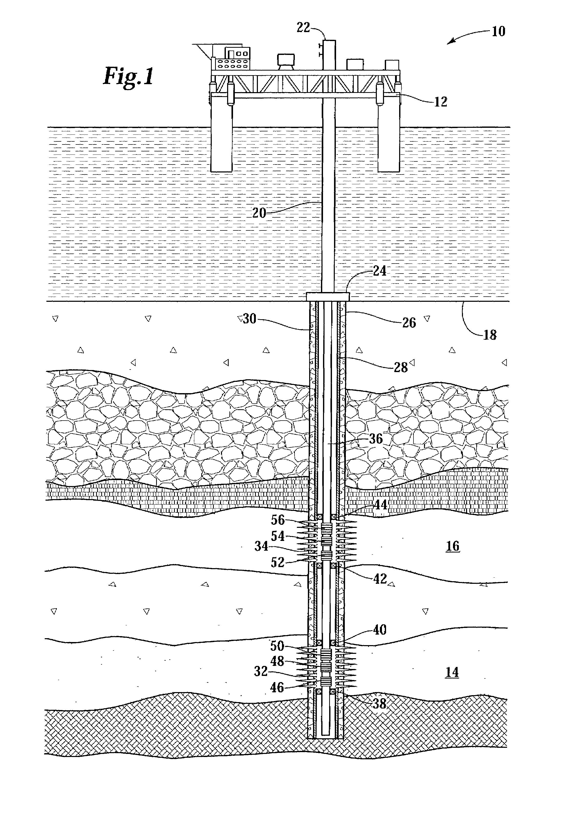
[0030]Referring initially to FIG. 1, an offshore oil and gas platform operating a plurality of fluid flow control devices is schematically illustrated and generally designated 10. A semi-submersible platform 12 is centered over submerged oil and gas formations 14, 16 located below sea floor 18. A subsea conduit 20 extends from a wellhead installation 22 to a subsea installation 24. A wellbore 26 extends through the various earth strata including formations 14, 16. A casing string 28 is cemented within wellbore 26 by cement 30. Casing string 28 includes ...


PUM


Abstract

A fluid flow control device (60) for use in a wellbore to control the inflow of production fluids comprises a sand control screen (62) having a base pipe (64) with a first set of openings (66) that allows the production fluids to flow therethrough and a sleeve (74) coaxially disposed adjacent to the base pipe (64). The sleeve (74) has a second set of openings (76) that allows the production fluids to flow therethrough. The sleeve (74) is selectively positionable relative to the base pipe (64) such that a pressure drop in the production fluids is selectively controllable by adjusting an alignment of the first set of openings (66) relative to the second set of openings (76).

Description

TECHNICAL FIELD OF THE INVENTION[0001]This invention relates, in general, to controlling the inflow of formation fluids from a well that traverses a hydrocarbon bearing subterranean formation and, in particular, to a fluid flow control device for controlling the inflow of formation fluids and a method for use of the same.BACKGROUND OF THE INVENTION[0002]Without limiting the scope of the present invention, its background will be described with reference to producing fluid from a subterranean formation, as an example.[0003]After drilling each of the sections of a subterranean wellbore, individual lengths of relatively large diameter metal tubulars are typically secured together to form a casing string that is positioned within each section of the wellbore. This casing string is used to increase the integrity of the wellbore by preventing the wall of the hole from caving in. In addition, the casing string prevents movement of fluids from one formation to another formation. Conventional...

Claims


Application Information

Patent Timeline
Patent Type & Authority Patents(United States)
IPC IPC(8): E21B43/12E21B43/08
CPCE21B43/12E21B43/08E21B47/09
Inventor ROSS, COLBY M.ECHOLS, RALPH H.WATSON, BROCK W.
Owner HALLIBURTON ENERGY SERVICES INC
Why Eureka
Try Eureka