Spectrograph with segmented dispersion device

Inactive Publication Date: 2007-02-08
ACTON R
View PDF15 Cites 22 Cited by
  • Summary
  • Abstract
  • Description
  • Claims
  • Application Information

AI Technical Summary

Benefits of technology

[0012] It is a further object of the present invention to provide a spectrograph that produces spectra with high resolution.
[0013] It is yet another object of the present invention to provide a spectrograph that does not result in nonlinearities or low light throughput.
[0014] It is still another object of the present invention to provide a spectrograph that does

Problems solved by technology

However, the modern sensors described above are sensitive to radiation in wide wavelength ranges that can extend from ultraviolet to infrared.
Traditional gratings, however, suffer from the fact that spectra from several spectral orders results in some ambiguities in the analysis of the spectrum.
This severely limits the spectral range for analysis, which is not useful for various forms of spectral analysis, such as atomic emission spectroscopy or Raman spectroscopy, which both require high resolution and coverage of a large spectral range.
However, while the echelle spectrograph produces high resolution and a large range by utilizing the vertical cross dispersion of the multi-order spectrum, it results in a number of disadvantages.
Specifically, these spectrographs suffer from nonlinearities and low light throughput, and they require complic

Method used


Image

  • Spectrograph with segmented dispersion device
  • Spectrograph with segmented dispersion device
  • Spectrograph with segmented dispersion device

Examples


Example

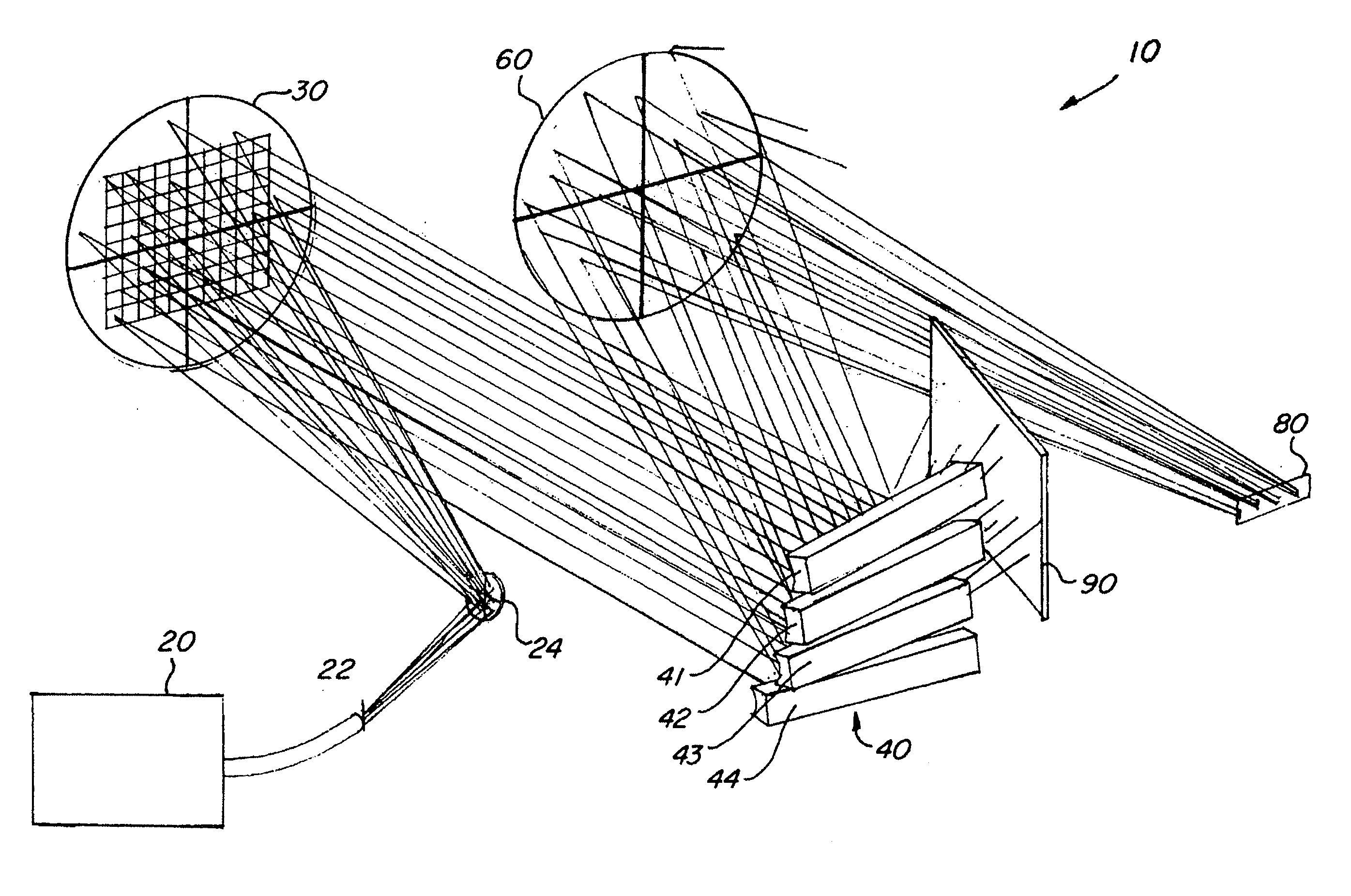
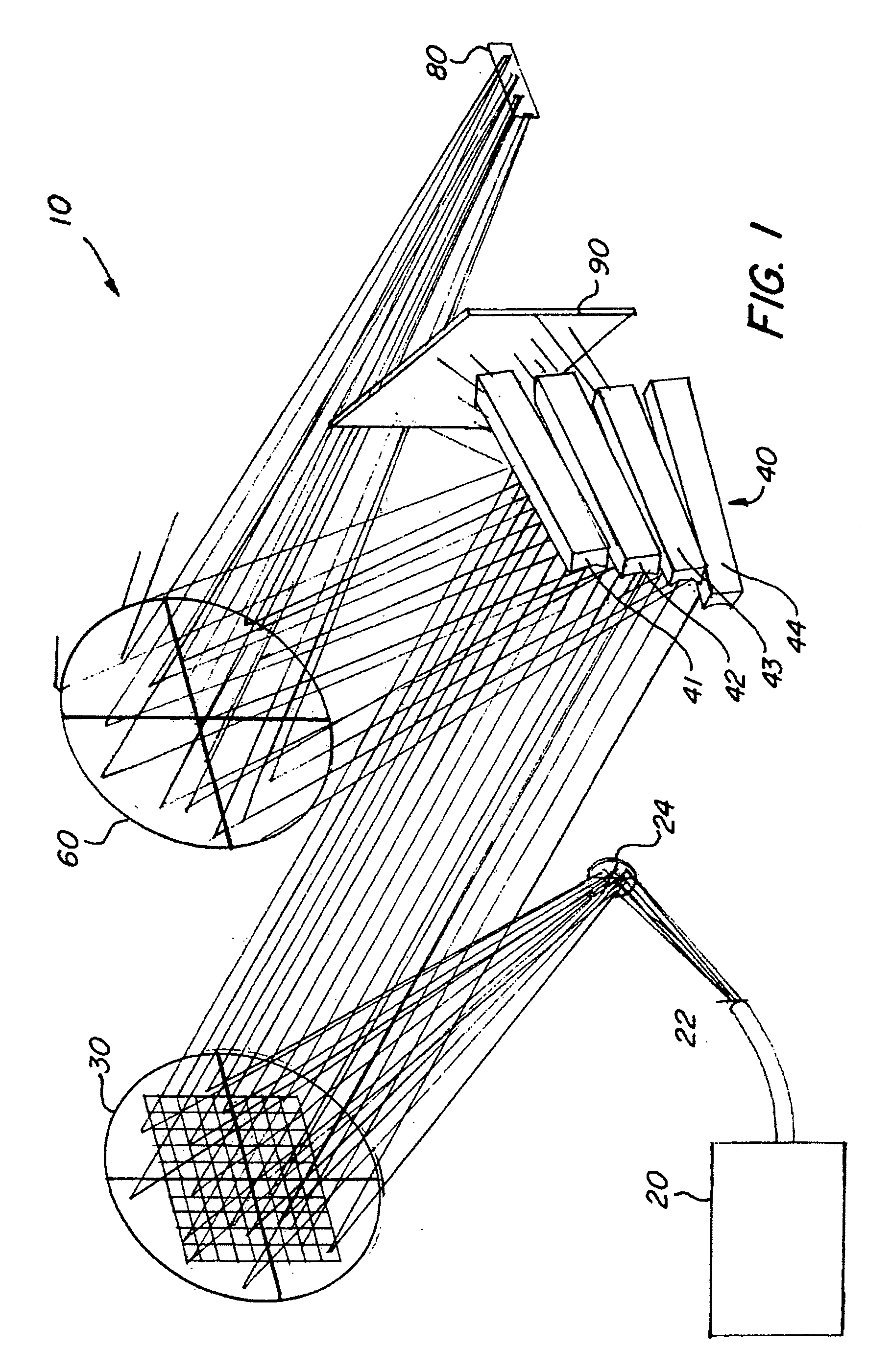
[0031] The basic components of one embodiment of a spectrograph with a segmented dispersion device in accordance with the invention are illustrated in FIG. 1. As used in the description, the terms “top,”“bottom,”“above,”“below,”“over,”“under,”“above,”“beneath,”“on top,”“underneath,”“up,”“down,”“upper,”“lower,”“front,”“rear,”“back,”“forward” and “backward” refer to the objects referenced when in the orientation illustrated in the drawings, which orientation is not necessary for achieving the objects of the invention.

[0032] The system 10 includes a light source 20, which may, for example, comprise a neon lamp, but which may be any source of radiation desired for a spectral analysis. The source 20 supplies the radiation via an entrance slit 22, which may, for example, be approximately 4 mm high. In some embodiments, this radiation exiting the entrance slit 22 is initially folded by a folding mirror 24.

[0033] The light is then directed to a collimator, such as a mirror 30, which colli...


PUM


Abstract

A spectrograph is disclosed generally comprising a radiation source and a dispersion device that includes a plurality of segments arranged adjacently along a plane upon which the radiation is incident, where each of the segments disperses the radiation differently than adjacent segments. In certain embodiments, each segment can be rotated and titled separately from the other segments. In some embodiments, the dispersed radiation is received by a detector in a plurality of spectral channels corresponding to the segments and including radiation of different spectral orders.

Description

CROSS-REFERENCE TO RELATED APPLICATIONS [0001] This patent application claims the benefit of, under Title 35, United States Code, Section 119(e), U.S. Provisional Patent Application No. 60 / 706,354, filed Aug. 8, 2005.FIELD OF THE INVENTION [0002] The present invention relates to a system for forming and recording the spectrum of a light source. More specifically, the invention relates to a spectrograph with an improved ability to segment and independently disperse various sub-ranges within the spectrum. BACKGROUND OF THE INVENTION [0003] Devices for performing spectral analyses, such as spectrographs, are generally well known in the art. Today, such devices employ image sensors, such as Charge Coupled Device (CCD) sensors, that are highly sensitive to wide spectrums. The use of these types of modern electronic detector arrays facilitates both rapid analog-to-digital data conversion and rapid processing of the large amounts of information that these image sensors will generate. In or...

Claims


Application Information

Patent Timeline
IPC IPC(8): G01J3/28
CPCG01J3/02G01J3/0202G01J3/36G01J3/06G01J3/18G01J3/0237
Inventor SOBCZYNSKI, RADOSLAW
Owner ACTON R
Why Eureka
Try Eureka