Method and apparatus for radial exhaust gas turbine

a technology of radial exhaust, which is applied in the direction of machines/engines, stators, liquid fuel engines, etc., can solve the problems of adversely affecting engine performance and/or engine efficiency, known gas turbine engines and known radial exhaust gas turbines that include an outer casing may experience high pressure losses in their exhaust diffuser sections

Inactive Publication Date: 2011-09-29
GENERAL ELECTRIC CO
View PDF11 Cites 196 Cited by
  • Summary
  • Abstract
  • Description
  • Claims
  • Application Information

AI Technical Summary

Problems solved by technology

At least some known gas turbine engines may experience high pressure losses.
Such pressure losses may adversely affect engine performance and/or engine efficiency.
For example, at least some known radial exhaust gas turbines that include an outer casing

Method used


Image

  • Method and apparatus for radial exhaust gas turbine
  • Method and apparatus for radial exhaust gas turbine
  • Method and apparatus for radial exhaust gas turbine

Examples


Embodiment Construction

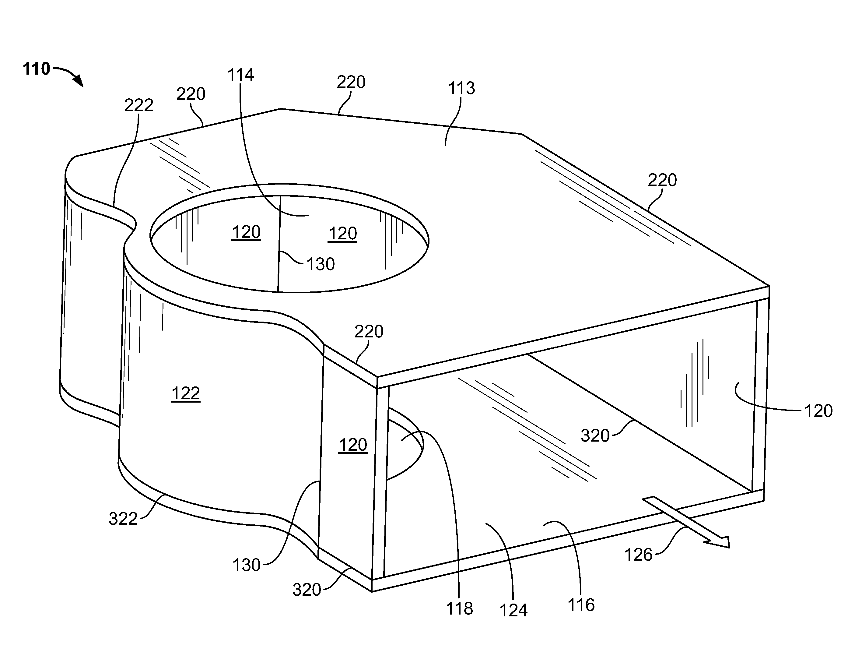
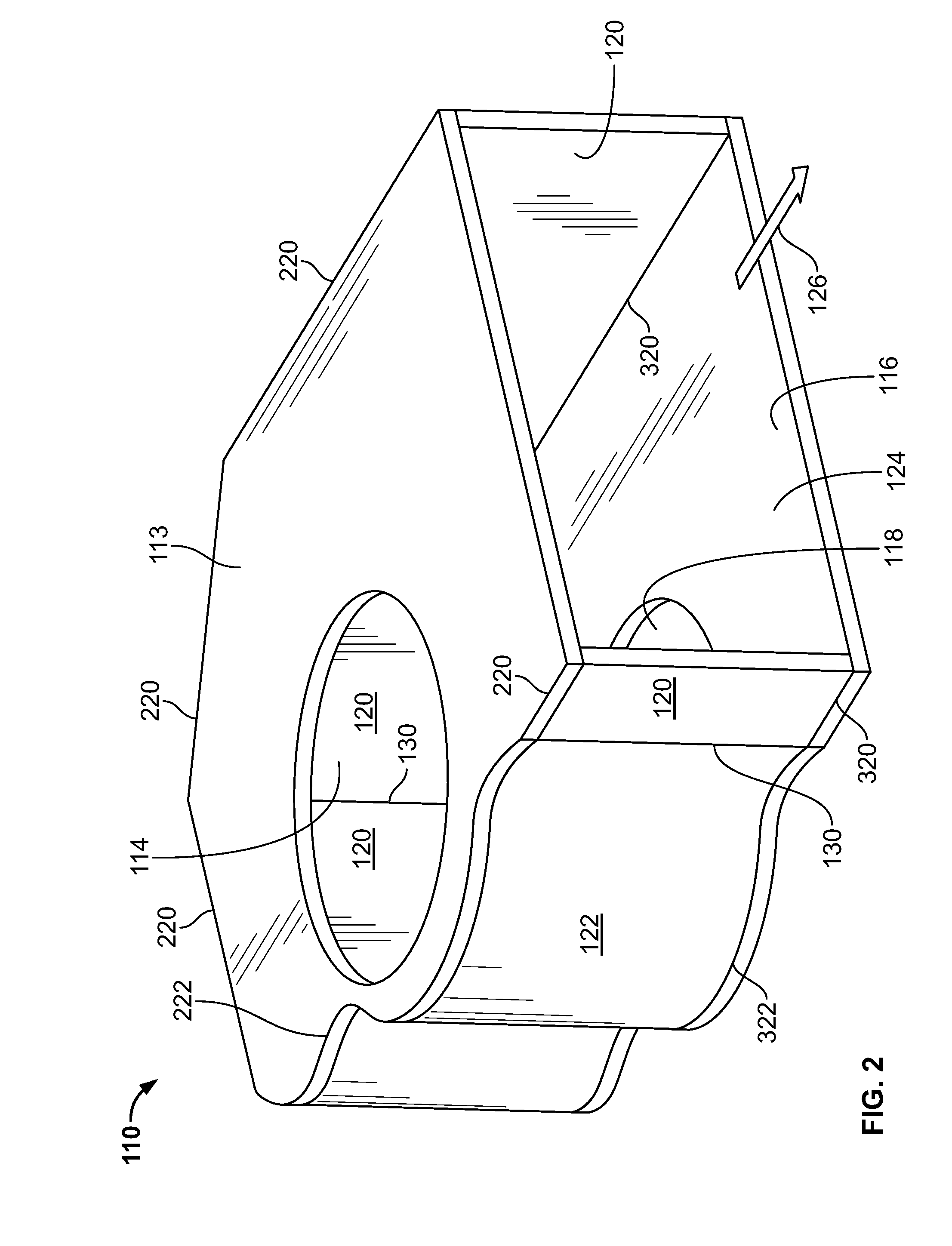
[0015]Embodiments of the present disclosure include an involute type casing for use with a radial exhaust diffuser of a gas turbine generator. The radial exhaust diffuser, when installed on the radial exhaust gas turbine facilitates reducing pressure loss in the casing generally, without increasing costs of manufacturing the casing. Flue gas discharged from vanes enters the casing and is directed towards one side of the casing.

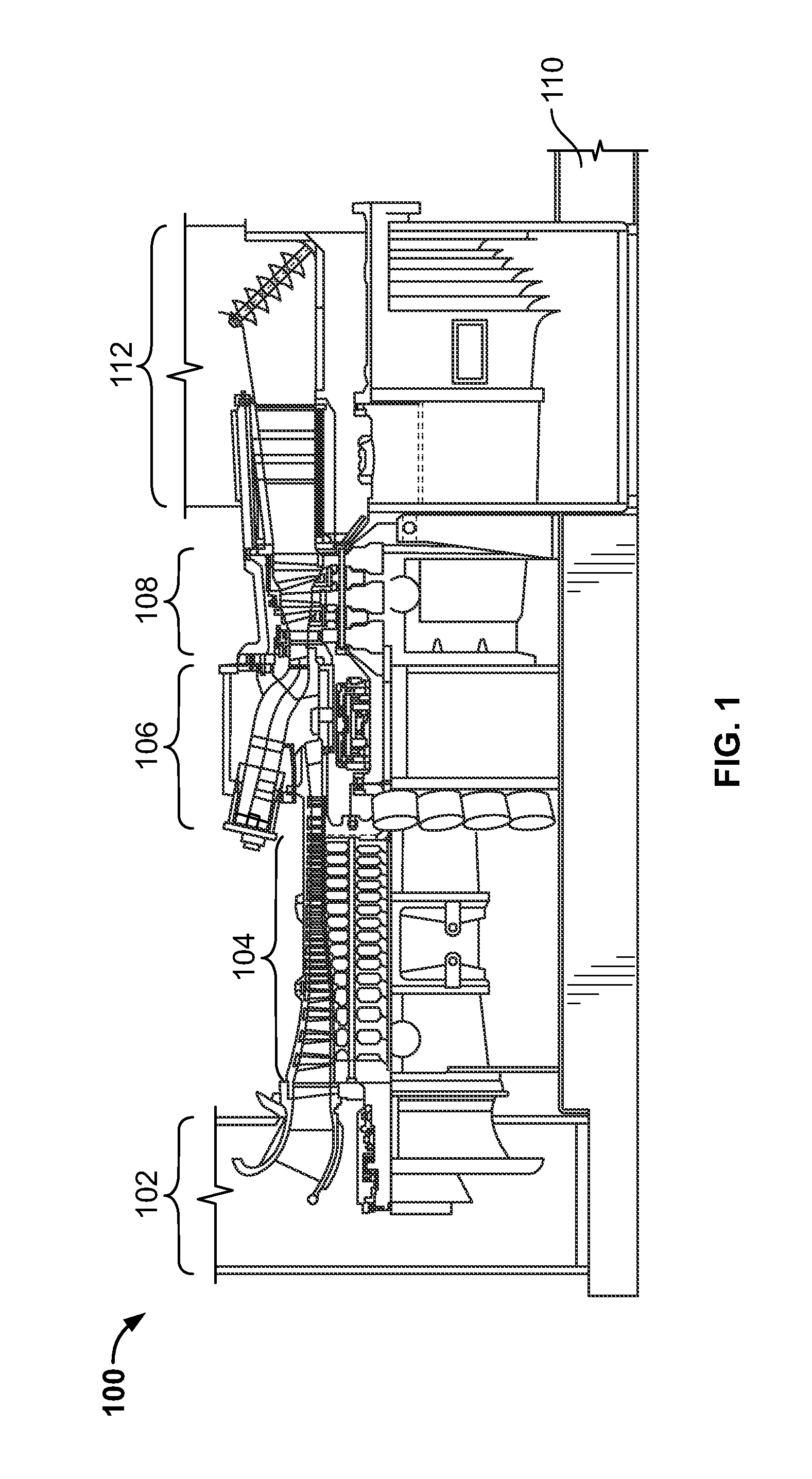
[0016]In some embodiments, and referring specifically to FIG. 1, a radial exhaust gas turbine 100 includes an inlet section 102, a compressor section 104, a combustor section 106, a turbine section 108, and an exhaust diffuser section 112. FIG. 2 and FIG. 3 illustrate respective triaxial and exploded triaxial views, respectively, of exhaust diffuser casing 110. In the illustrated embodiment, exhaust diffuser casing 110 includes a turbine engagement wall 113 that includes an entry opening 114. An exhaust diffuser engagement wall 116 is positioned opposite turbi...


PUM


Abstract

A radial exhaust gas turbine apparatus has a gas turbine engine that includes a radial exhaust diffuser section and a casing apparatus consisting essentially of polygonal walls, substantially straight plates, and substantially straight sidewalls. The casing apparatus encloses the radial exhaust diffuser section and is configured to direct at least a substantial portion of the gas exiting the radial exhaust diffuser section to an exit in the casing apparatus via an approximately involute path.

Description

BACKGROUND OF THE INVENTION[0001]The field of the present invention relates generally to gas turbine generators, and more specifically to involute type casings for use with radial exhaust gas turbines.[0002]At least some known gas turbine engines may experience high pressure losses. Such pressure losses may adversely affect engine performance and / or engine efficiency. For example, at least some known radial exhaust gas turbines that include an outer casing may experience high pressure losses in their exhaust diffuser sections. Although circular outer casings can be used to reduce this pressure drop, such casings may be expensive to manufacture, especially for gas turbines that require large size casings.[0003]It would therefore be desirable to provide a more efficient and less expensive casing for use with gas turbines that include a radial exhaust. In particular, it would be desirable to provide a casing that reduces pressure losses in the outer casing section while not being relat...

Claims


Application Information

Patent Timeline
IPC IPC(8): F04D29/44
CPCF01D25/30
Inventor SHENDE, SUMEDHKUMAR VYANKATESH
Owner GENERAL ELECTRIC CO
Why Eureka
Try Eureka