Detector of infrared radiation having a bi-material transducer

a transducer and detector technology, applied in the direction of optical elements, instruments, optical radiation measurement, etc., can solve the problems of heavy detectors, relatively expensive, bulky, etc., and achieve the effect of large ir fill factor

Inactive Publication Date: 2009-08-25
ALCATEL-LUCENT USA INC
View PDF27 Cites 10 Cited by
  • Summary
  • Abstract
  • Description
  • Claims
  • Application Information

AI Technical Summary

Benefits of technology

[0009]A representative embodiment of the invention provides an infrared (IR) detector having a movable plate supported at an offset distance from a substrate by a suspension arm. In response to a temperature difference between the plate and the substrate generated by the incident IR radiation, the suspension arm deforms and changes the offset distance for the plate. In one embodiment, the suspension arm has three rod-shaped bimorph transducers that lie within a plane that is parallel to the substrate. The transducers are also parallel to one another, with the transducer that is attached to an anchor of the suspension arm being located between the two transducers that are attached to the plate. Advantageously, this transducer arrangement in a suspension arm compensates the adverse effects of ambient temperature variations, creates a well-balanced plate with just one suspension arm, and enables an array of IR detectors to have a relatively large IR fill factor.

Problems solved by technology

As such, photonic IR detectors utilize cryostats and / or complex cooling systems, which make these detectors heavy, bulky, and relatively expensive.

Method used


Image

  • Detector of infrared radiation having a bi-material transducer
  • Detector of infrared radiation having a bi-material transducer
  • Detector of infrared radiation having a bi-material transducer

Examples


Embodiment Construction

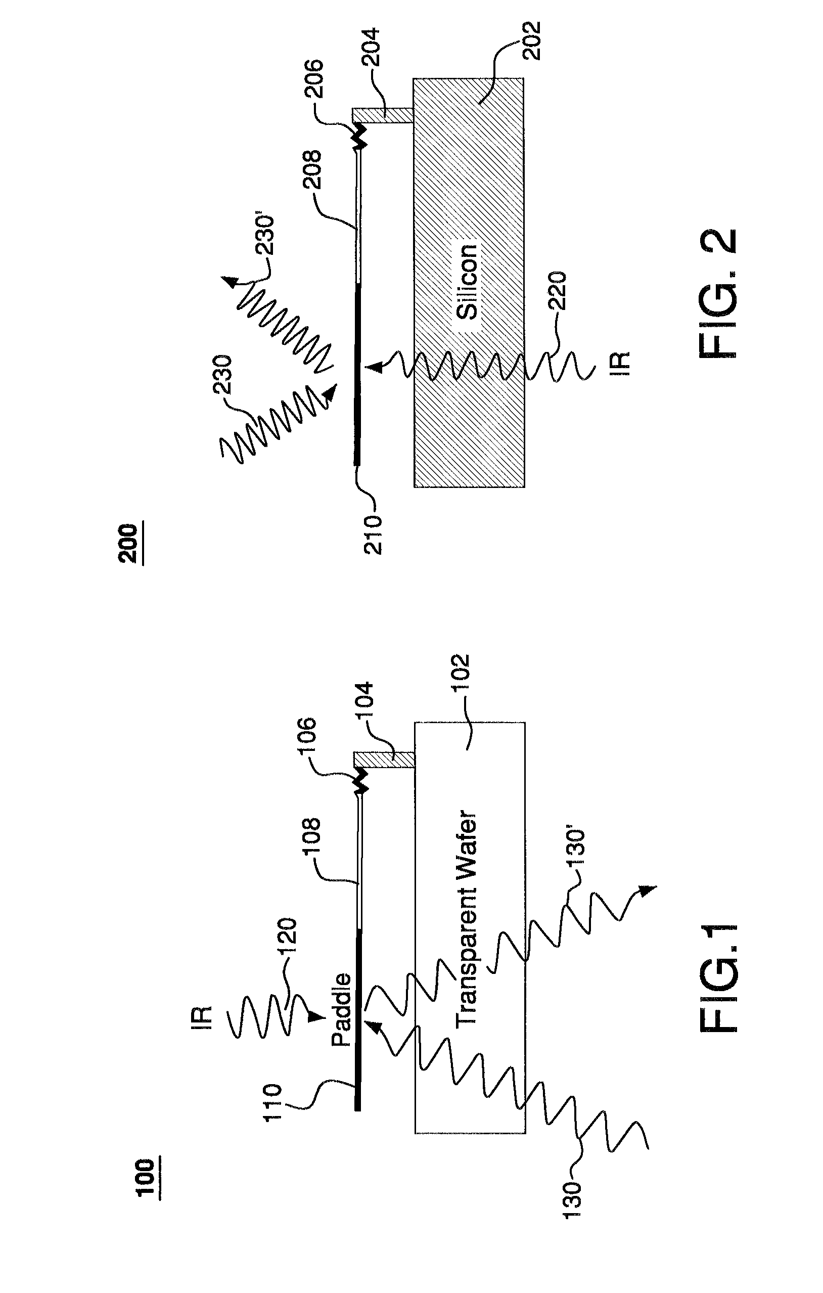
[0032]The operating principles of an infrared (IR) detector having a bi-material cantilever is described, e.g., in an article by S. R. Hunter, R. A. Amantea, L. A. Goodman, et al., entitled “High Sensitivity Uncooled Microcantilever Infrared Imaging Arrays,” published in Proceedings of SPIE, 2003, v. 5074, pp. 469-480, the teachings of which are incorporated herein by reference. Briefly, the detector typically has (1) an IR-radiation absorbing area, (2) a bi-material element, and (3) a thermal isolator. The IR-radiation absorbing area converts the impinging IR radiation into heat, while the thermal isolator prevents the heat from being shunted to the substrate. The two materials forming the bi-material element are selected to have a large difference in their thermal-expansion coefficients. As the temperature of the bi-material element increases due to the IR heating, the material having the larger thermal-expansion coefficient attempts to expand a greater amount than the adjacent ma...


PUM


Abstract

A representative embodiment of the invention provides an infrared (IR) detector having a movable plate supported at an offset distance from a substrate by a suspension arm. In response to a temperature difference between the plate and the substrate generated by the incident IR radiation, the suspension arm deforms and changes the offset distance for the plate. In one embodiment, the suspension arm has three rod-shaped bimorph transducers that lie within a plane that is parallel to the substrate. The transducers are also parallel to one another, with the transducer that is attached to an anchor of the suspension arm being located between the two transducers that are attached to the plate.

Description

CROSS-REFERENCE TO RELATED APPLICATIONS[0001]The subject matter of this application is related to that of U.S. patent application Ser. No. 11 / 766,430, entitled “Infrared Imaging Apparatus” by Vladimir Aksyuk, Cristian Bolle, Christopher Jones, Flavio Pardo, Roland Ryf, and Maria Elina Simon, which is being filed on the same date as the present U.S. patent application.[0002]This application is also related to U.S. patent application Ser. No. 11 / 713,207, filed Mar. 2, 2007, and entitled “Direct Optical Image Projectors.” The two above-identified U.S. Patent Applications are incorporated herein by reference in their entirety.BACKGROUND OF THE INVENTION[0003]1. Field of the Invention[0004]The present invention relates to detectors of infrared radiation and infrared imaging systems.[0005]2. Description of the Related Art[0006]Infrared (IR) detectors are classified into two categories: photonic and thermal. In a photonic IR detector, infrared photons are absorbed to excite electronic tran...

Claims


Application Information

Patent Timeline
Patent Type & Authority Patents(United States)
IPC IPC(8): G02B26/00G01J5/00
CPCG01J5/40
Inventor AKSYUK, VLADIMIR ANATOLYEVICHBOLLE, CRISTIAN A.JONES, CHRISTOPHER D. W.PARDO, FLAVIORYF, ROLANDSIMON, MARIA ELINA
Owner ALCATEL-LUCENT USA INC
Why Eureka
Try Eureka