Lighting device

a technology of light source and light source, which is applied in the direction of lighting elements, semiconductor devices for light sources, lighting and heating apparatus, etc., can solve problems such as system energy loss, and achieve the effect of improving extraction efficiency and reducing the probability of reabsorption

Active Publication Date: 2009-11-10
CREELED INC
View PDF170 Cites 326 Cited by
  • Summary
  • Abstract
  • Description
  • Claims
  • Application Information

AI Technical Summary

Benefits of technology

[0027]The general object of the present invention is to maximize the light extraction from the solid state light emitter (e.g., light emitting diode chip) or the package (e.g., LED package) in such devices.
[0028]In the case of conventional LED packages which include a phosphor, a significant proportion (e.g., in many cases, as much as 20% to 25%) of the excitation light (i.e., light from the LED) is reflected (back scattered) from the phosphor back into the light emitting diode chip / package. Back scattered light which is scattered back into the light emitting diode chip itself has a very low probability of coming out of the chip, and hence, such back scattering results in a system loss of energy.
[0030]Furthermore, if the luminescent element is too thick, and / or if the luminescent material (e.g., phosphor) content in the luminescent element is too great, “self-absorption” may occur. Self-absorption occurs when light emissions within the packaging layer stay within the packaging layer to excite other phosphor particles and eventually are absorbed or are otherwise prevented from exiting the device, thus reducing performance (intensity) and efficiency. Additionally, if the particle size of the luminescent material (e.g., phosphors) is too large, the particles of luminescent material can cause unwanted scattering of both the excitation source (the LED chip) and the light generated by the phosphor.
[0031]In accordance with one aspect of the present invention, by spatially separating the solid state light emitter from the luminescent element, this extraction efficiency can be improved. In addition, by making the surface area of the illumination surface of the solid state light emitter which faces the luminescent element much smaller than the surface area of the luminescent element which faces the solid state light emitter, any backscatter light from the excitation source or any emitted light from the luminescent element has a lower probability of reabsorption in the solid state light emitter.

Problems solved by technology

Back scattered light which is scattered back into the light emitting diode chip itself has a very low probability of coming out of the chip, and hence, such back scattering results in a system loss of energy.

Method used


Image

  • Lighting device
  • Lighting device

Examples


Embodiment Construction

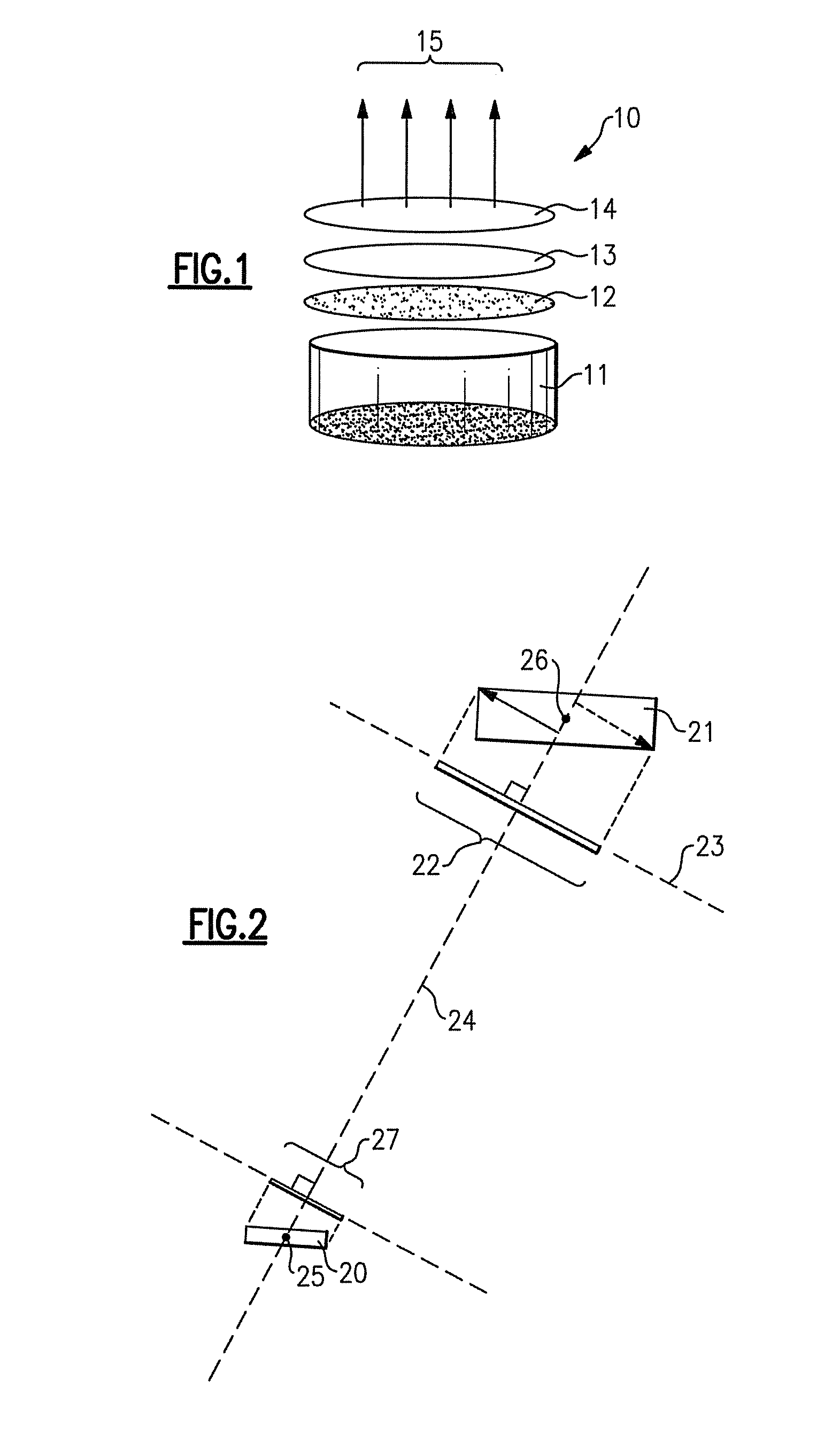
[0052]As noted above, in accordance with various aspects of the present invention, there is provided a lighting device comprising at least one solid state light emitter and at least one luminescent element, the luminescent element comprising at least one luminescent material.

[0053]Any desired solid state light emitter or emitters can be employed in accordance with the present invention. Persons of skill in the art are aware of, and have ready access to, a wide variety of such emitters. Such solid state light emitters include inorganic and organic light emitters. Examples of types of such light emitters include light emitting diodes (inorganic or organic), laser diodes and thin film electroluminescent devices, a variety of each of which are well-known in the art. As noted above, a wide variety of luminescent materials (also known as lumiphors or luminophoric media, e.g., as disclosed in U.S. Pat. No. 6,600,175, the entirety of which is hereby incorporated by reference) are well-known...


PUM


Abstract

A lighting device comprising at least one solid state light emitter and at least one luminescent element spaced from the light emitter, a surface of the luminescent element being at least twice as large as the illumination surface of the light emitter. Also, a lighting device comprising at least one solid state light emitter and at least one luminescent element spaced from the light emitter, a surface of the luminescent element surface being at least twice as large as and substantially parallel to the illumination surface of the light emitter. Also, a lighting device comprising at least one solid state light emitter and at least one luminescent element spaced from the light emitter, a surface area of a projection of the luminescent element being at least twice as large as a surface area of a projection of the light emitter.

Description

CROSS-REFERENCE TO RELATED APPLICATIONS[0001]This application claims the benefit of U.S. Provisional Patent Application No. 60 / 753,138, filed Dec. 22, 2005, the entirety of which is incorporated herein by reference.[0002]This application claims the benefit of U.S. Provisional Patent Application No. 60 / 831,775, filed Jul. 19, 2006, the entirety of which is incorporated herein by reference.FIELD OF THE INVENTION[0003]The present invention relates to a lighting device, in particular, a device which includes one or more solid state light emitters and one or more luminescent materials (e.g., one or more phosphors). In a particular aspect, the present invention relates to a lighting device which includes one or more light emitting diodes, and one or more luminescent materials.BACKGROUND OF THE INVENTION[0004]A large proportion (some estimates are as high as one third) of the electricity generated in the United States each year goes to lighting. Accordingly, there is an ongoing need to pro...

Claims


Application Information

Patent Timeline
Patent Type & Authority Patents(United States)
IPC IPC(8): F21V33/00H01L33/50
CPCH01L33/505F21K9/00F21K9/56F21V9/16H01L2924/0002F21Y2101/02H01L2924/00F21V29/67F21K9/64F21Y2115/10F21V9/30H01L33/507F21V13/14
Inventor NEGLEY, GERALD H.
Owner CREELED INC
Why Eureka
Try Eureka