Method and apparatus for automated, digital, radiographic inspection of piping

a radiographic inspection and radiographic technology, applied in the direction of measuring devices, scientific instruments, instruments, etc., can solve the problems of anomalies and flaws, internal and external corrosion, piping is vulnerable to attack, etc., to save inspection time, high speed, and accurate images

Active Publication Date: 2010-02-02
ALREJA VIJAY
View PDF4 Cites 76 Cited by
  • Summary
  • Abstract
  • Description
  • Claims
  • Application Information

AI Technical Summary

Benefits of technology

[0008]The invention described below provides a system and a method for high speed radiographic inspection of piping that can be used in remote locations on insulated pipe of varying diameters, providing highly accurate images on all portions of the piping by its ability to rotate circumferentially around the piping. The radiation source and detector are supported on an inner carriage in such a way that they are perfectly aligned with each other. The inner carriage is capable of 360 degree rotations around the pipe and is supported by an outer carriage that rests on the piping. The inner and outer carriages are concentric with each other and are both located outside the piping. The inner and outer carriages are open on one end to enable placement of the system at any location on the piping. The inner carriage is designed such that it is always supported by the outer carriage during the 360 degree rotation around the piping. In operation means are provide to rotate the inner carriage in either the clock wise or the counter clockwise direction. Sensing devices are...

Problems solved by technology

Piping is vulnerable to attack by internal and external corrosion, cracking, mechanical damage and manufacturing flaws in the manufacturing process as well as needs to remain undamaged during use in the field.
Anomalies and flaws can be caused during manufacturing and need to be discovered prior to installation.
In addition, physical, chemical and electrolytic actions can cause flaws such as cracks after installation and therefore regular inspection is required to ensure safe operation.
This layer of insulation makes it more difficult to inspect t...

Method used


Image

  • Method and apparatus for automated, digital, radiographic inspection of piping
  • Method and apparatus for automated, digital, radiographic inspection of piping
  • Method and apparatus for automated, digital, radiographic inspection of piping

Examples


Embodiment Construction

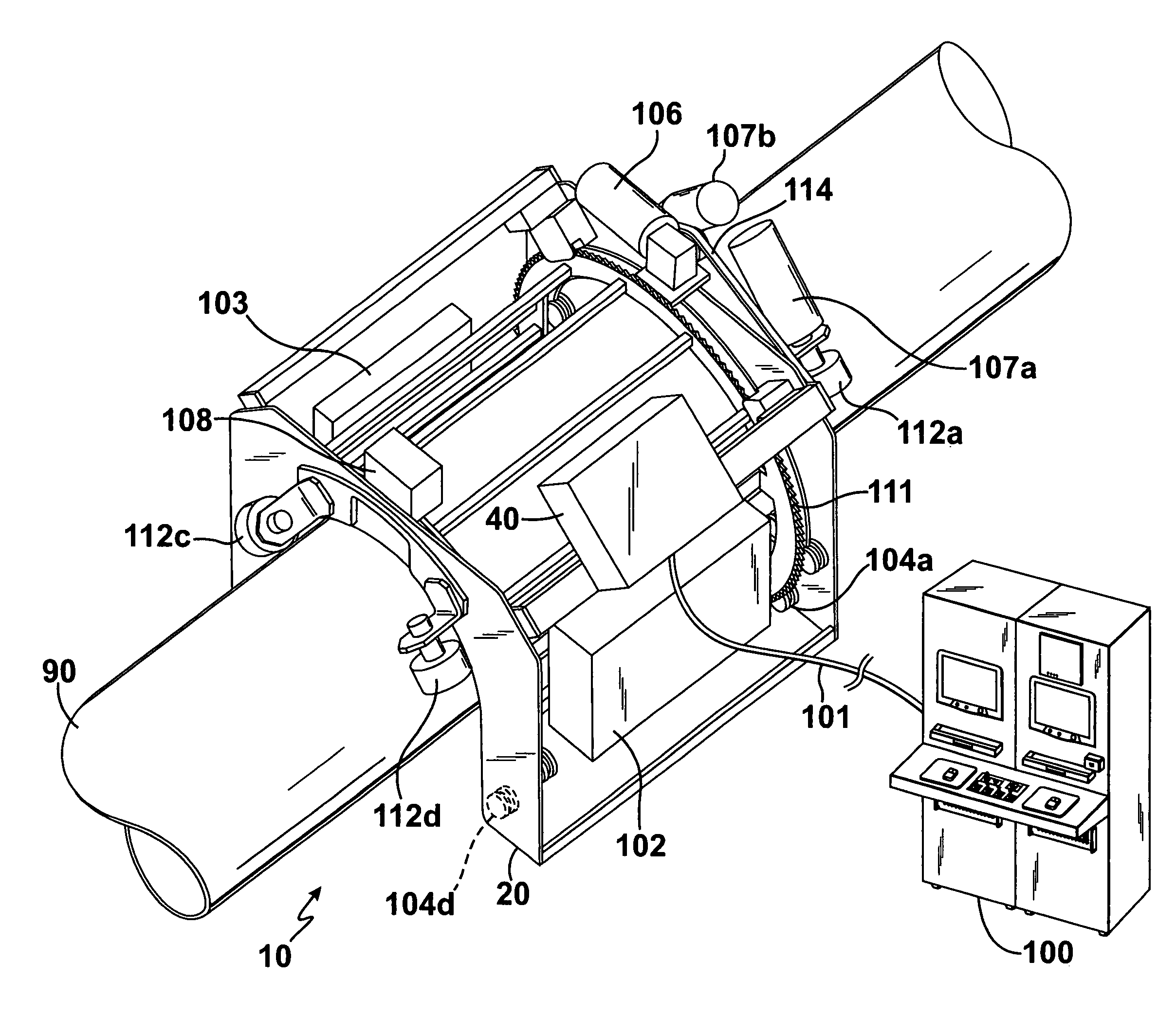
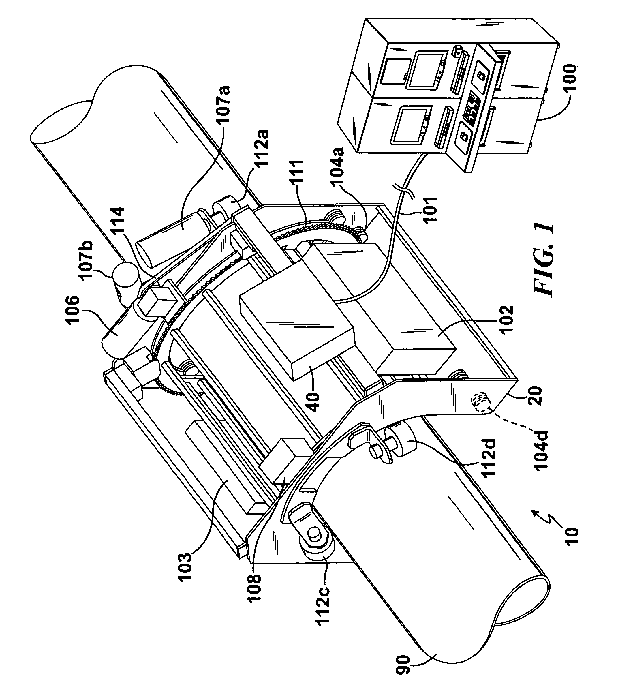
[0043]Referring to the drawings wherein identical reference numerals denote the same elements throughout the various views. FIG. 1 shows the system for x-ray inspection of piping. As mentioned before this system is not restricted to piping and could also be used for inspecting other cylindrical fluid transport vessels such as heat exchangers and silo sections. The system can be used to inspect piping prior to installation although its greatest utility is to measure insulated piping after installation.

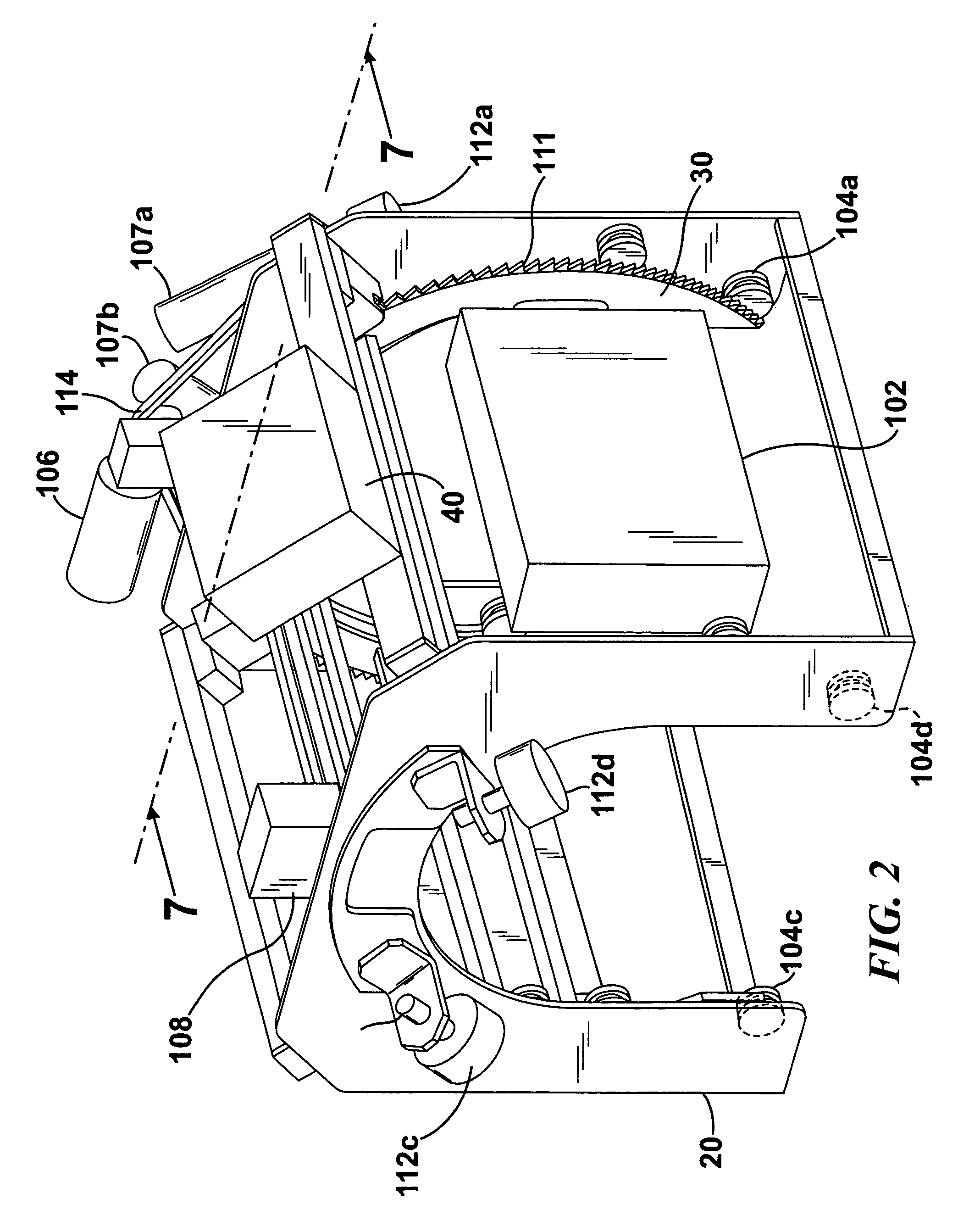
[0044]FIG. 1 shows the system mounted on the piping. FIGS. 2, 3 and 4 show the openings in the bottom portions of the inner carriage 30 and outer carriage 20 that allows the system to be placed on the piping. As best shown in FIG. 4 the outer carriage is provided with four critical support rollers 104a, 104b, 104c and 104d. Two rollers are attached to one end frame of the outer carriage and two are attached to the opposite end frame of the outer carriage. The distance between the two se...


PUM


Abstract

A system and method for automatic digital radiographic inspection of piping in which a radiation source and radiation detector are mounted on an inner carriage that rotates concentrically inside an outer carriage and both carriages are placed externally to the piping during operation. A rotating system is provided to cause the inner carriage to rotate completely around the piping. A positioning system is provided for moving the outer carriage longitudinally on the piping. A balancing system is provided such that any tilting of the system during its longitudinal movement on the piping is corrected. In operation, the system is placed on the piping and the rotating system causes the inner carriage to rotate around the piping. After one complete rotation is ensured the positioning system moves the assembly in a longitudinal direction on the piping. A controller controls the rotating; positioning and balancing systems in a coordinated manner to move the outer carriage after the inner carriage has made one complete rotation of the piping. The radiation detector receives the data signals form the radiation source and these signals are used to generate images of the piping for inspection of defects.

Description

FEDERAL SPONSORED RESEARCH[0001]Not ApplicableSEQUENCE LISTING OR PROGRAM[0002]Not ApplicableFIELD OF INVENTION[0003]This invention relates to automatic radiographic inspection and automated image acquisition of piping and other cylindrical vessels used for fluid transport. Fluids such as crude oil, petroleum products, natural gas and other chemicals are transported in piping that is subject to damage in the structure caused by physical, chemical, and electrolytic actions. These actions can weaken the structural integrity of the piping or vessel and can result in oil and chemical spills that cause environmental damage and also can result in fires and explosions. To ensure that the vessel or pipe can continue to be used safely ongoing nondestructive testing is required.BACKGROUND OF THE INVENTION[0004]The greatest utility of the invention described in this specification is for inspection of piping, but the invention can be used to inspect other types of hollow containers such as heat...

Claims


Application Information

Patent Timeline
IPC IPC(8): G01N23/02
CPCG01N23/04G01N2223/628
Inventor ANJELLY, SAMIR
Owner ALREJA VIJAY
Why Eureka
Try Eureka