

Apparatus and method for clock data recovery with low lock frequency
a clock data and lock frequency technology, applied in the field of clock data recovery, can solve the problems of increasing the power consumption of the cdr circuit for such high clock frequency, and the difficulty in designing the vco to generate a clock signal with substantially higher clock frequency, and achieves low cost, low power dissipation, and easy implementation.
- Summary
- Abstract
- Description
- Claims
- Application Information
AI Technical Summary
Benefits of technology
Problems solved by technology
Method used
Image



Examples
Embodiment Construction
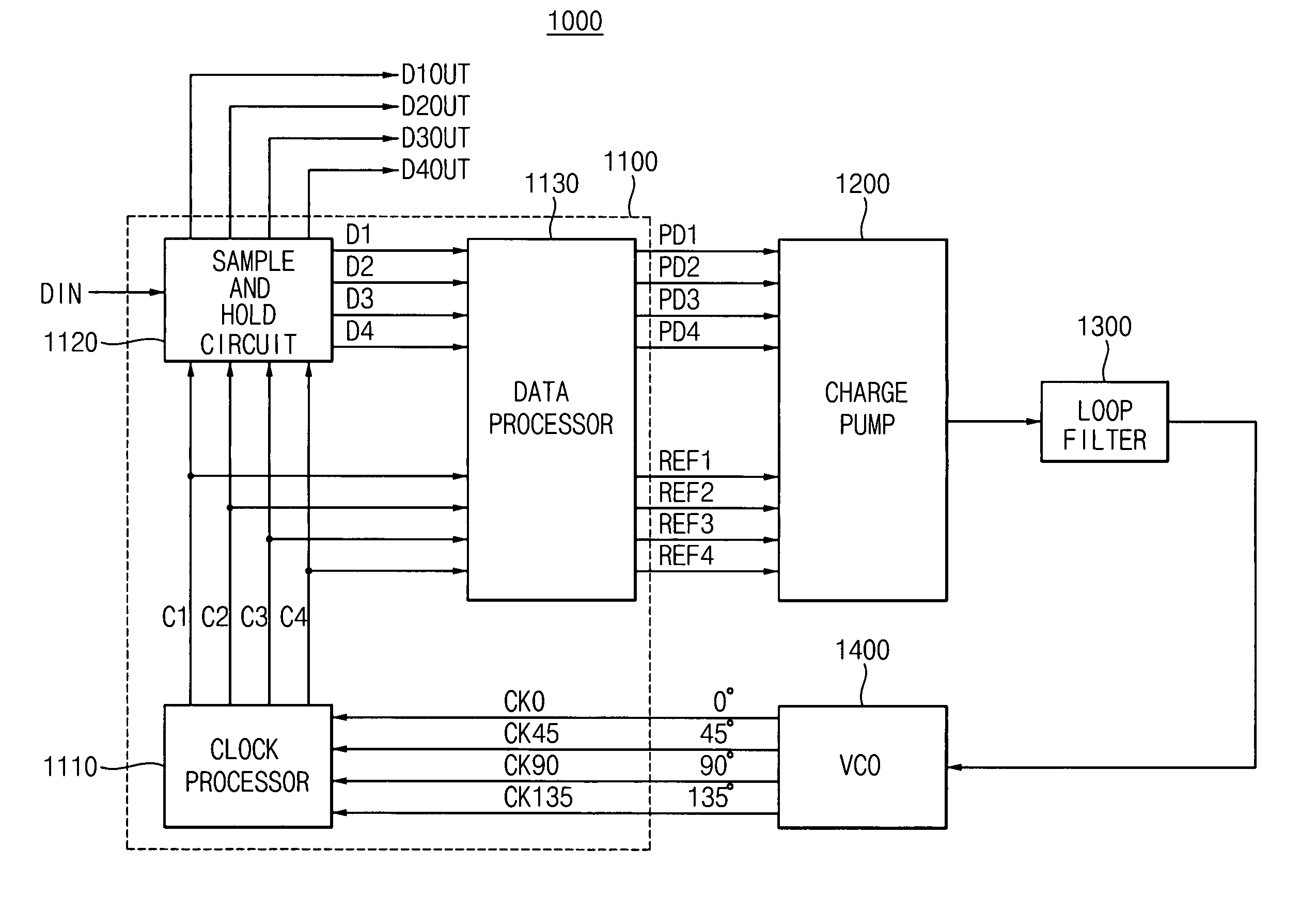
[0038]FIG. 3 is a block diagram of a clock and data recovery (CDR) apparatus 1000 according to an example embodiment of the present invention. Referring to FIG. 3, the CDR apparatus 1000 includes a voltage-controlled oscillator (VCO) 1400, a phase detector 1100, a charge pump 1200, and a loop filter 1300.
[0039]The VCO 1400 generates multiphase clock signals CKO, CK45, CK90 and CK135 that are phase-shifted with respect to each other. A clock frequency of each of the clock signals CKO, CK45, CK90 and CK135 is determined by a control voltage VCON from the loop filter 1300.
[0040]In addition, the clock frequency of each of the multiphase clock signals CKO, CK45, CK90 and CK135 is ⅛ of a frequency of an input data signal DIN. Thus, each of the multiphase clock signals CKO, CK45, CK90 and CK135 has a period eight times longer than a period of the input data signal DIN.
[0041]Furthermore, the clock signals CKO, CK45, CK90 and CK135 are successively phase-shifted by 45-degrees from each-other...
PUM
 Abstract
Description
Claims
Application Information